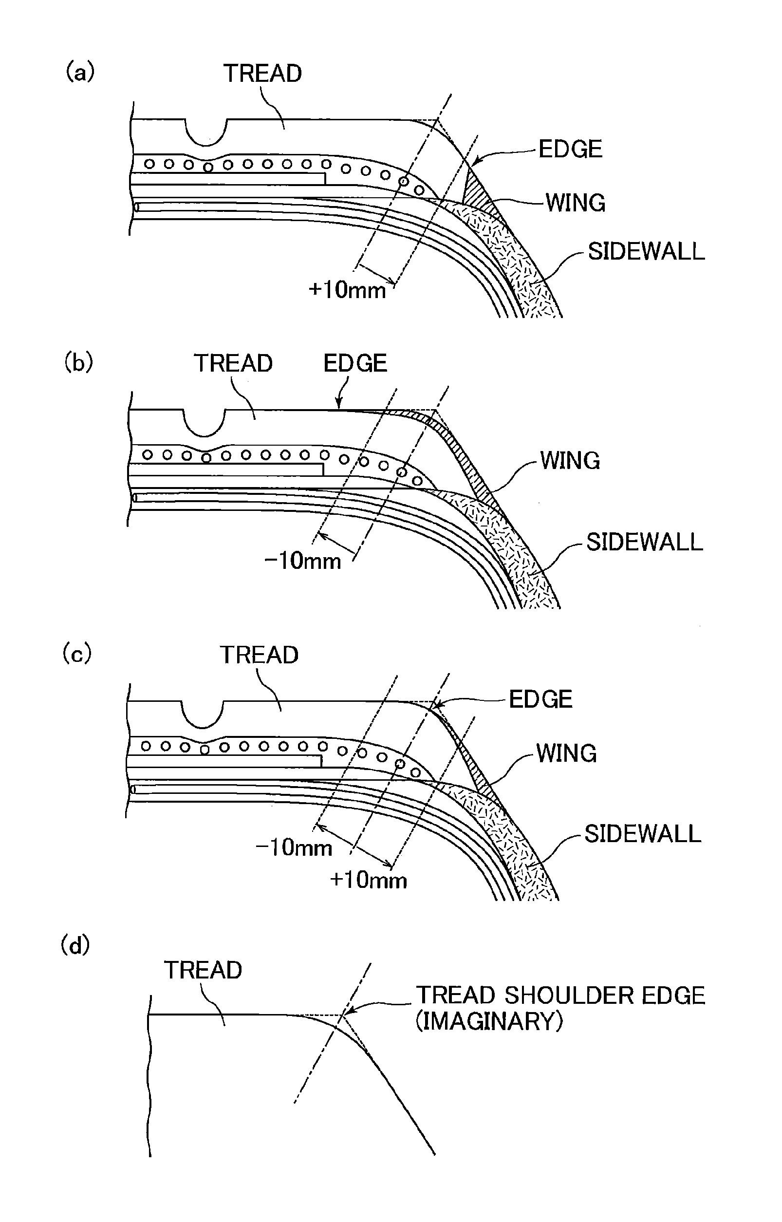
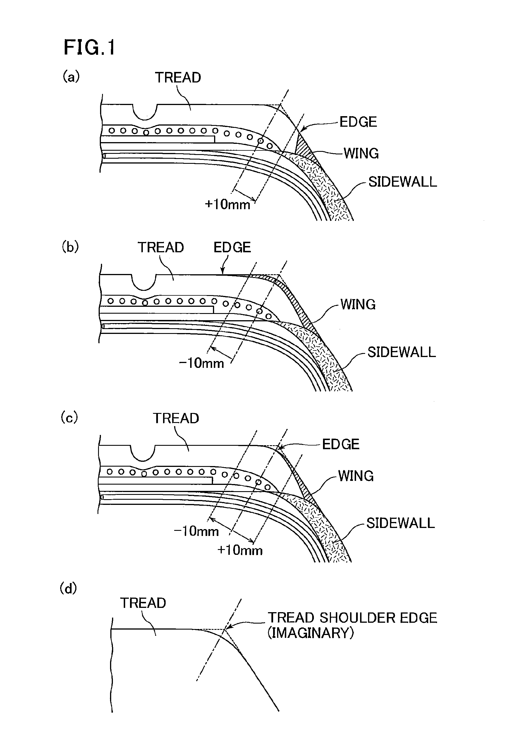
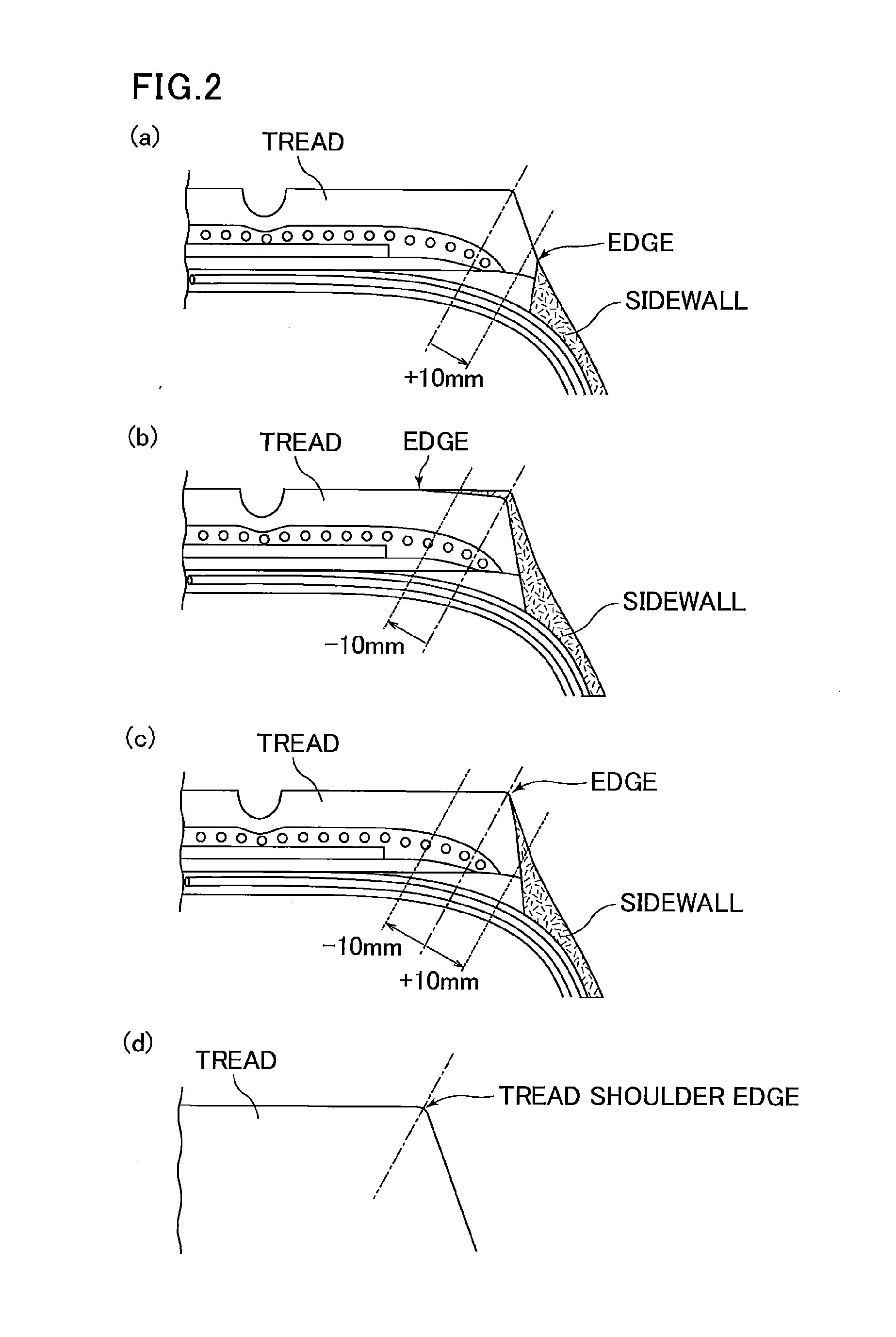
Pneumatic tire

a pneumatic tire and tire body technology, applied in the field of pneumatic tires, can solve the problems of peeling, curling, peeling, and the finish bonding surface between the tread and its adjacent wing or sidewall after vulcanization is sometimes in poor condition, and achieves excellent finish bonding surfa

Inactive Publication Date: 2014-05-29
SUMITOMO RUBBER IND LTD
View PDF6 Cites 4 Cited by
  • Summary
  • Abstract
  • Description
  • Claims
  • Application Information

AI Technical Summary

Benefits of technology

The technical effect of this patented technology relates to improving the quality of rubber-tired wheels by controllably reducing their content of vulcanizing agent (cross linking) during manufacturing without compromising on their durability for use at high speeds.

Problems solved by technology

The technical problem addressed in this patents relates to improving the quality of final assembly when assembling together different parts made up of these materials into an airless tire without compromising any desired properties like durability under specific conditions.

Method used


Image

  • Pneumatic tire
  • Pneumatic tire
  • Pneumatic tire

Examples


examples

[0061]The present invention is more specifically described with reference to examples of tires for passenger vehicles with a TOS structure, but the present invention is not limited to these examples.

Preparation of Terminal Modifier

[0062]A measuring flask (100-mL) was charged with 23.6 g of 3-(N,N-dimethylamino)propyltrimethoxysilane (AZmax. Co.) in a nitrogen atmosphere, and was further charged with anhydrous hexane (Kanto Chemical Co., Inc.) to thereby prepare a terminal modifier in a total amount of 100 mL.

Copolymer Preparation 1

[0063]A sufficiently nitrogen-purged, pressure-resistant vessel (30-L) was charged with 18 L of n-hexane (Kanto Chemical Co., Inc.), 2000 g of butadiene (Takachiho Trading Co., Ltd.), and 2 mmol of tetramethylethylenediamine (Kanto Chemical Co., Inc.), and then the temperature was raised to 60° C. Next, 10.3 mL of butyllithium (Kanto Chemical Co., Inc.) was added to the mixture, and then the temperature was raised to 50° C., followed by stirring for three hou


PUM

PropertyMeasurementUnit
Percent by massaaaaaaaaaa

Abstract

The present invention provides a pneumatic tire having an excellent finished bonding surface between the tread and its adjacent wing or sidewall while maintaining required performance of a tire such as abrasion resistance and resistance to degradation over time. The present invention relates to a pneumatic tire including a tread and a wing or sidewall adjacent to the tread, wherein the tread is formed from a rubber composition for a tread which has a specific net sulfur content derived from crosslinking agents; the wing or sidewall is formed from a rubber composition for a wing or sidewall which has a specific net sulfur content derived from crosslinking agents; and a specific relationship is satisfied between the net sulfur content derived from crosslinking agents in the rubber composition for a tread and the net sulfur content derived from crosslinking agents in the rubber composition for a wing or sidewall.

Description


Claims


Application Information

Patent Timeline
Owner SUMITOMO RUBBER IND LTD
Why Eureka
Try Eureka