Removing device and removing method for particulate pollutants generated by combustion of biomass fuel

A biomass fuel and pollutant technology, applied in separation methods, chemical instruments and methods, and separation of dispersed particles, can solve complex problems such as water inflow and outflow, and achieve the effects of reducing exhaust gas temperature and reducing water pollution

Active Publication Date: 2014-07-09
SHANDONG JIANZHU UNIV
View PDF9 Cites 1 Cited by
  • Summary
  • Abstract
  • Description
  • Claims
  • Application Information

AI Technical Summary

Benefits of technology

This patented technology helps remove particles like dust or harmful gases (like nitrogen oxide) out of fossil fuels during burning without causing damage. By continuously reducing the moisture content inside the furnace while it runs through, this process improves efficiency and prevents environmental problems such as acid rain caused by excessive humidity.

Problems solved by technology

This patented technical problem addressed in this patent relates to finding an efficient way to remove small amounts of harmful substances such as nitrous oxides or arsenic compounds during the production of biofuled materials like biodiesel due to their negative environmental impact. Current methods involve burning them away at significant costs while ignoring beneficial uses. There exists a challenge towards developing simpler and better ways to efficiently separate these harmful constituents from the material being processed.

Method used


Image

  • Removing device and removing method for particulate pollutants generated by combustion of biomass fuel
  • Removing device and removing method for particulate pollutants generated by combustion of biomass fuel
  • Removing device and removing method for particulate pollutants generated by combustion of biomass fuel

Examples


Embodiment Construction

[0031] The present invention will be further described below in conjunction with the accompanying drawings:

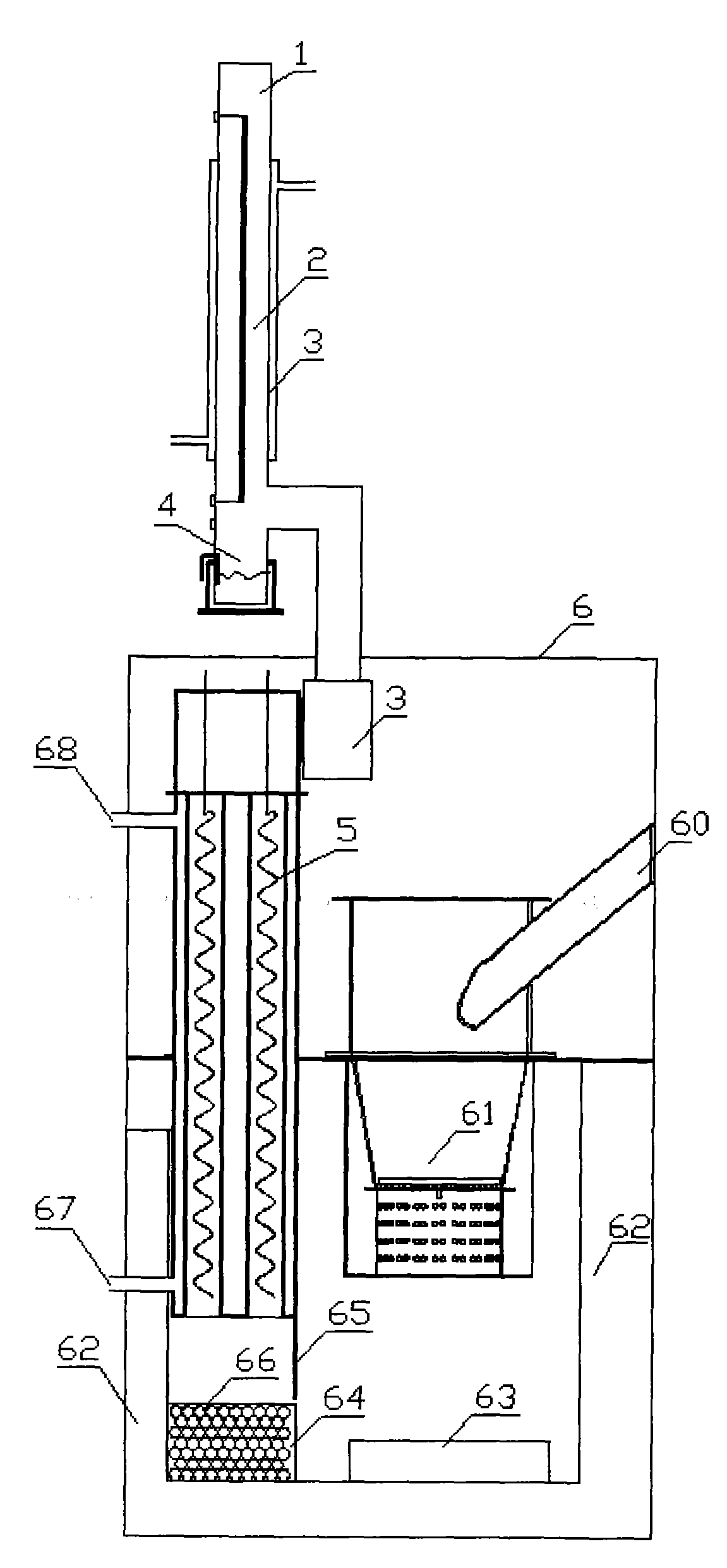
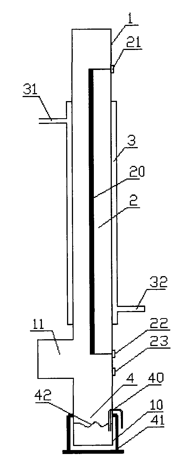
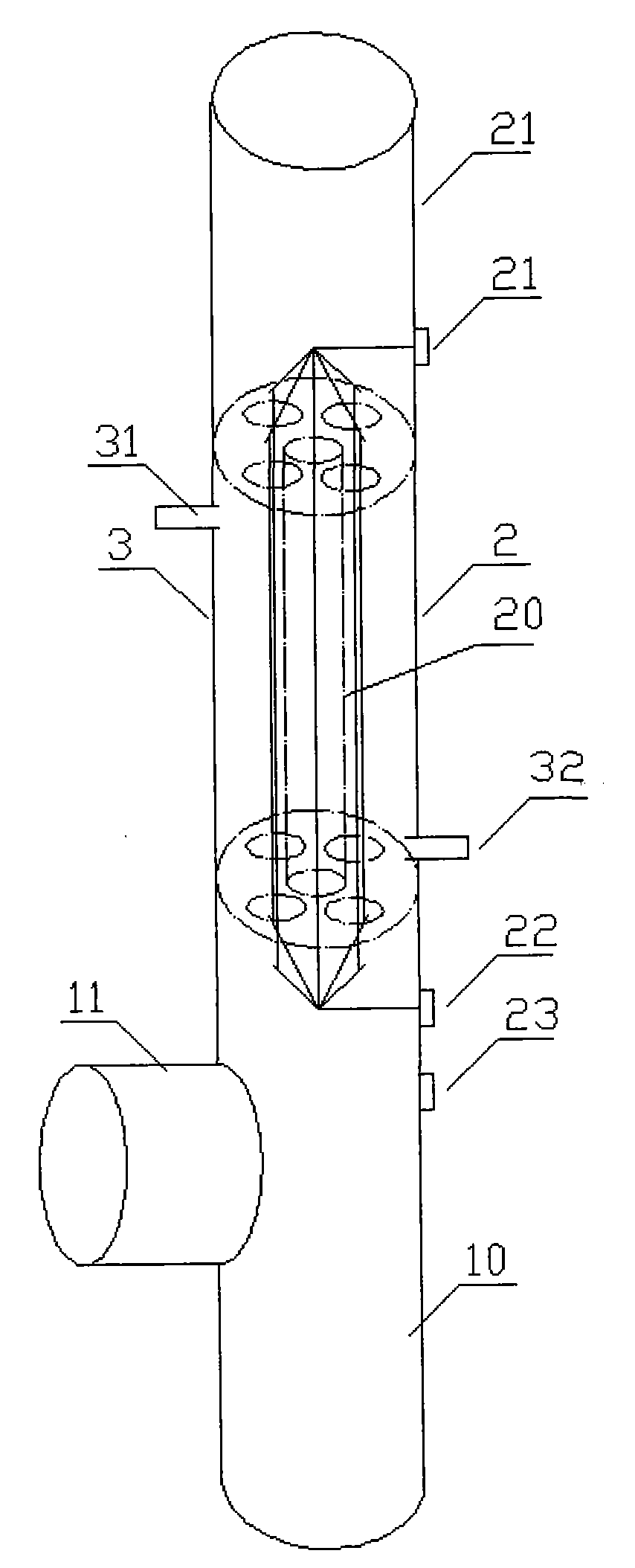
[0032] like Figure 1 to Figure 4 Shown: a biomass fuel combustion particle pollutant removal device according to the present invention includes a chimney 1, a wet electrostatic precipitator 2, a flue gas condenser 3, a wet ash cleaning device 4, a spiral ash cleaning device 5, a combustion The chamber 61 and the heating furnace shell 6 are arranged in the chimney 1, the flue gas condenser 3 is sleeved outside the chimney 1, the wet ash cleaning device 4 is arranged at the lower end of the chimney 1, the flue gas condenser 3 and the spiral ash cleaning device 5 are connected. The upper ends are connected, the combustion chamber 61 and the spiral ash cleaning device 5 are both arranged in the heating furnace shell 6 , and the combustion chamber 61 is provided with a feeding port 60 which communicates with the inside and outside of the heating furnace shell 6 .

[0033] li


PUM


Abstract

The invention discloses a removing device and a removing method for particulate pollutants generated by combustion of biomass fuel. The removing device comprises a chimney, a wet-type electric dust remover, a smoke condenser, a wet-type ash remover, a spiral ash remover, a combustion chamber and a heating furnace shell. The wet-type electric dust remover is arranged in the chimney. The smoke condenser sleeves the chimney. The wet-type ash remover is arranged at the lower end of the chimney. The smoke condenser is connected with the upper end of the spiral ash remover. The combustion chamber and the spiral ash remover are arranged in the heating furnace shell. A feed port communicated with the inside and the outside of the heating furnace shell is arranged on the combustion chamber. Smoke contains a large quantity of steam after the biomass fuel combusts, the steam can be condensed to form a thin water film on the surface of a precipitation pole when the temperature of the smoke continues dropping, and a cooling water jacket is arranged on the outer portion of the precipitation pole, so that exhaust smoke temperature is reduced, and heat of the smoke is recycled; condensed water generated by condensation serves as a water source of the wet-type electric dust remover, so that a water adding device, a water spraying device and the like are omitted, and water pollution is reduced.

Description


Claims


Application Information

Patent Timeline
Owner SHANDONG JIANZHU UNIV
Why Eureka
Try Eureka