Intelligent ocean oil spill detection method for remote sensing large image

An intelligent detection and large image technology, applied in the field of remote sensing image processing, can solve the problems of high complexity of the entire image, low detection efficiency, and difficult detection accuracy, and achieve the effect of improving detection efficiency and detection accuracy

Inactive Publication Date: 2014-08-06
INST OF REMOTE SENSING & DIGITAL EARTH CHINESE ACADEMY OF SCI
View PDF1 Cites 14 Cited by
  • Summary
  • Abstract
  • Description
  • Claims
  • Application Information

AI Technical Summary

Problems solved by technology

[0005] The current existing oil spill detection algorithms based on SAR data rely partially or entirely on manual interpretation for the identification of oil slicks, which has low work efficiency and high false alarm rate
With the commercial operation of satellite SAR, the number of SAR images has increased sharply. At the same time, my country has a vast territorial sea, with nearly 3 million square kilometers of jurisdictional sea area, and the problem of marine oil spill

Method used


Image

  • Intelligent ocean oil spill detection method for remote sensing large image
  • Intelligent ocean oil spill detection method for remote sensing large image
  • Intelligent ocean oil spill detection method for remote sensing large image

Examples


Embodiment Construction

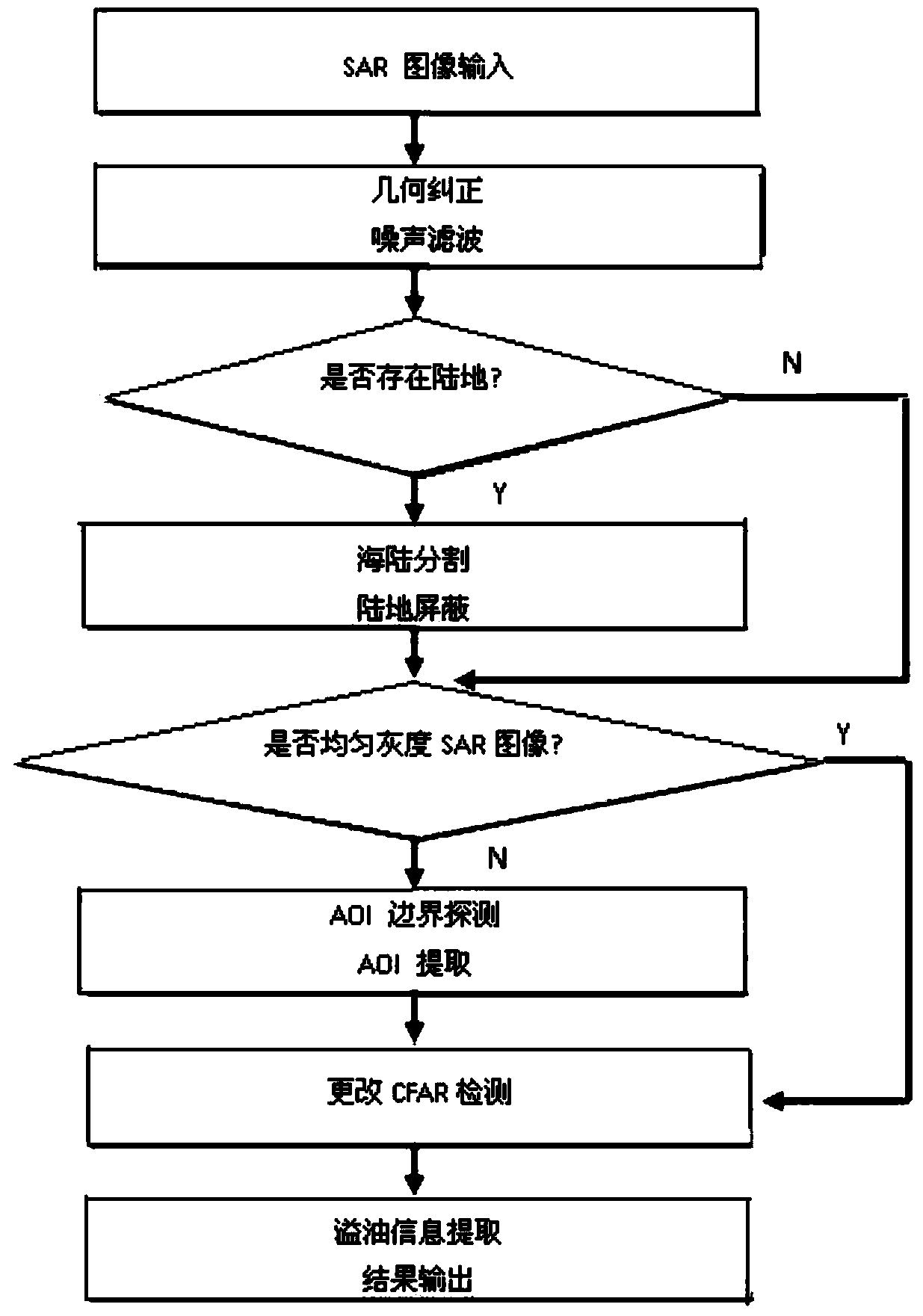
[0037] Such as figure 1 As shown in Fig. 1, geometric correction and noise filtering are performed on the input SAR image, and then sea and land segmentation is performed to shield the land influence; then, for the whole scene image, the approximate position of the oil slick is monitored by using the ratio edge detection (ROA), and it is marked as a spill. Oil suspected area (AOI), and then apply the improved CFAR detection algorithm to these AOIs for adaptive partition detection, detect the final oil spill area, and extract relevant information. This method can better adapt to the complex and localized situation of the sea surface background in SAR images, and obtain high-precision detection results. Specifically include the following steps:

[0038] Step 1: Precise processing of the whole scene image: including SAR image LEE and MAP Gamma filtering, geometric correction, etc.;

[0039] Step 2: Separation of sea and land, shielding land. Apply Markov random field theory to se


PUM


Abstract

The invention relates to an intelligent ocean oil spill detection method for a remote sensing large image. The method includes the following steps of (1) remote sensing large image input and processing; (2) AOI detection of suspected oil spill areas; (3) oil spill area extraction based on CFAR. The intelligent ocean oil spill detection method for the remote sensing large image has the advantages of greatly improving detection efficiency and detection accuracy of ocean oil spill of the remote sensing large image.

Description


Claims


Application Information

Patent Timeline
Owner INST OF REMOTE SENSING & DIGITAL EARTH CHINESE ACADEMY OF SCI
Why Eureka
Try Eureka