Feeding device for electric power copper pipe flaring machine

A flaring machine and copper tube technology, applied in the field of tube material processing, can solve the problems of many sources of failure, long length and large space occupation, and achieve the effect of improving processing efficiency

Inactive Publication Date: 2014-09-24
STATE GRID CORP OF CHINA +1
View PDF8 Cites 3 Cited by
  • Summary
  • Abstract
  • Description
  • Claims
  • Application Information

AI Technical Summary

Benefits of technology

This technology uses an inclined tube that helps it move materials smoothly without getting stuck or damaging them during production. It also makes sure they are being processed properly by allowing for automatic movement between different stations within the system.

Problems solved by technology

This patented problem with current piping flare machines involves their size in terms of length or volume that makes it difficult to improve upon them due to factors like costs associated with manufacturing materials used during production.

Method used


Image

  • Feeding device for electric power copper pipe flaring machine
  • Feeding device for electric power copper pipe flaring machine
  • Feeding device for electric power copper pipe flaring machine

Examples


Embodiment 1)

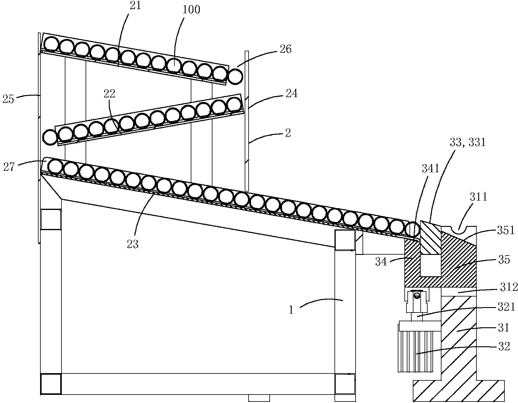
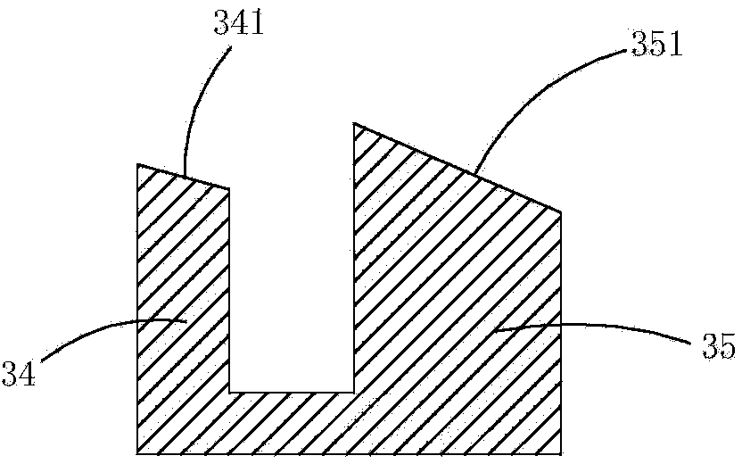
[0015] figure 1 with figure 2 A specific embodiment of the present invention is shown, in which, figure 1 Is a schematic diagram of the structure of the present invention; figure 2 for figure 1 A structural schematic diagram of the feeding top column and the discharging top column in the ejecting device shown.

[0016] This embodiment is a feeding device for the electric copper pipe flaring machine, see Figure 1 to Figure 2 As shown, the bracket 1, the feeding mechanism 2 and the ejecting mechanism 3 are included.

[0017] The conveying mechanism includes a first conveying plate 21, a second conveying plate 22, a third conveying plate 23, a front baffle 24 and a rear baffle 25, the first conveying plate, the second conveying plate, and the The cross-sectional shape of the three conveying plates is U-shaped; the first conveying plate, the second conveying plate, and the third conveying plate are all inclined at an angle with the horizontal plane, and combined to form an inclined Z-sh


PUM


Abstract

The invention discloses a feeding device for an electric power copper pipe flaring machine. The feeding device comprises a supporting part, a material jack air cylinder, a separating part, a feeding jack prop and discharging jack prop. The supporting part is fixedly arranged on a support. The separating part is arranged between the supporting part and a material conveying mechanism, and a material moving slope is arranged on the top wall of the separating part. The feeding jack prop and the discharging jack prop are fixedly arranged on a piston of the material jack air cylinder. A feeding slope is arranged on the top wall of the feeding jack prop, and a material jack through hole matched with the feeding jack prop is formed in the front end of the material conveying mechanism. The feeding jack prop penetrates upwards through the material jack through hole under the driving of the piston of the material jack air cylinder and jacks up a material pipe adjacent to the separating part in the material conveying mechanism. A sliding chute is formed in the top wall of the supporting part, and the discharging jack prop moves up and down along the sliding chute under the driving of the piston of the material jack air cylinder. A discharging face inclined downwards to the front from the rear is arranged on the top wall of the discharging jack prop. According to the feeding device for the electric power copper pipe flaring machine, automatic feeding and discharging in a rolling mode are achieved by using the self-gravity of material pipes, and thus the machining efficiency is effectively improved.

Description


Claims


Application Information

Patent Timeline
Owner STATE GRID CORP OF CHINA
Why Eureka
Try Eureka