Ink box chip, ink box and structural body

A technology of ink cartridge chip and structure, which is applied in the field of inkjet printers, can solve the problems that it is difficult to ensure good contact of ink cartridge chip printer contact pins, and achieve the effect of reducing positioning accuracy requirements and improving stability

Active Publication Date: 2014-11-26
ZHUHAI NINESTAR MANAGEMENT CO LTD
View PDF8 Cites 7 Cited by
  • Summary
  • Abstract
  • Description
  • Claims
  • Application Information

AI Technical Summary

Benefits of technology

This technology allows for better control over an electronic printing machine's print quality when it uses different types or sizes of toner. By placing containers at one end onto another side of the printed material, there will also reduce their size, making them easier to connect correctly without being too big compared to other parts of the system.

Problems solved by technology

This patented technical problem addressed by the present inventors relates to ensuring proper alignment during loading of inking cartridles onto print machines due to their size and shape.

Method used


Image

  • Ink box chip, ink box and structural body
  • Ink box chip, ink box and structural body
  • Ink box chip, ink box and structural body

Examples


Embodiment 1

[0033] This embodiment provides an ink cartridge chip, which is suitable for ink cartridges, especially for ink cartridges of inkjet printers. The ink cartridge chip of this embodiment is detachably mounted on the ink cartridge.

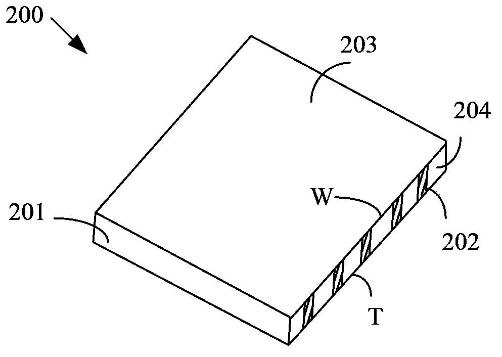
[0034] Such as figure 2 Shown is a schematic diagram of the three-dimensional structure of the ink cartridge chip according to this embodiment. The cartridge chip 200 of this embodiment includes a circuit board 201 and a plurality of container-side terminals 202 .

[0035] Wherein, the circuit board 201 includes a first plane 203 and a second plane 204 perpendicular to the first plane 203, the surface area of ​​the second plane 204 is smaller than the surface area of ​​the first plane 203; each container side terminal 202 is arranged on the second plane 204 , and one end of each container-side terminal 202 intersects the first plane 203, the other end of each container-side terminal 202 intersects a third plane (not shown in the figure), the third pl

Embodiment 2

[0040] This embodiment provides an ink cartridge chip based on the first embodiment.

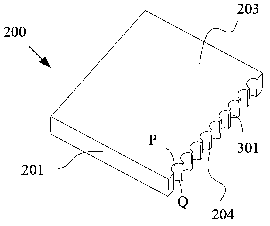
[0041] Such as Figure 3A As shown, it is a schematic diagram of the three-dimensional structure of the ink cartridge chip 200 according to this embodiment; Figure 3B As shown, it is a schematic top view structure diagram of the ink cartridge chip 200 according to this embodiment; Figure 3C Shown is a left view of the ink cartridge chip 200 according to this embodiment, as Figure 3D Shown is a schematic diagram of the second plane 204 of the ink cartridge chip 200 according to this embodiment.

[0042] The second plane 204 of the ink cartridge chip 200 of this embodiment includes a plurality of grooves 301, and a container-side terminal 202 is arranged in each groove 301, that is, the number of the grooves 301 is consistent with the number of the container-side terminals 202. The number of slots 301 may also be more or less than the number of container-side terminals 202 . Specifically,


PUM


Abstract

Disclosed are an ink box chip (200), an ink box (400), and a structural body (700). The ink box chip comprises a circuit board (201) and at least two container side terminals (202) used for contacting apparatus side terminals (500). The circuit board comprises a first plane (203) and a second plane (204) perpendicularly intersecting with the first plane, and the superficial area of the second plane is smaller than the superficial area of the first plane. The container side terminals are disposed on the second plane. One ends of the container side terminals intersect with the first plane, and the other ends of the container side terminals intersect with a third plane. The third plane is opposite to the first plane. The container side terminals are disposed on the second plane with a smaller superficial area on the circuit board, and the container side terminals penetrate the second plane and are arranged into a row, the apparatus side terminals easily contact the container side terminals, thereby improving the stability of an electrical connection between an ink box and a printer.

Description


Claims


Application Information

Patent Timeline
Owner ZHUHAI NINESTAR MANAGEMENT CO LTD
Why Eureka
Try Eureka