LED panel lamp structure with novel lighting manner

Inactive Publication Date: 2014-12-10
JIANGSU TIWIN OPTO ELECTRONICS TECH
View PDF9 Cites 4 Cited by
  • Summary
  • Abstract
  • Description
  • Claims
  • Application Information

AI Technical Summary

Benefits of technology

Problems solved by technology

This patented technical problem addressed by this patents describes how current LED panels have complex construction that requires expensive material for assembly while still providing excellent performance at low levels of intensity without causing discomfort over longer periods of use due to their poor optical properties.

Method used


Image

  • LED panel lamp structure with novel lighting manner
  • LED panel lamp structure with novel lighting manner

Examples


Embodiment Construction

[0020] The following will clearly and completely describe the technical solutions in the embodiments of the present invention with reference to the drawings in the embodiments of the present invention.

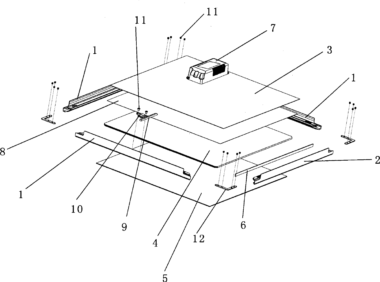
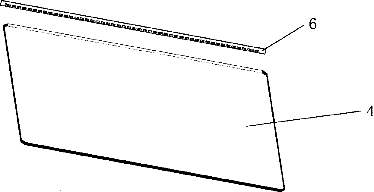
[0021] Such as figure 1 , 2 As shown, the present invention provides a LED panel light structure with a new light output mode, the panel light includes a frame 1, a back plate 3, a light guide plate 4, a diffusion plate 5, a light source plate 6 and a driver 7, and the light source plate 6. Paste on one of the frame I2 with heat-conducting double-sided adhesive tape as the light-incoming side; the surface of the light guide plate 4 is pasted with a layer of reflective film 8, so that the light returns to the light guide plate 4 and is evenly distributed on the light guide plate 4 to emit light from the front , the diffuser plate 5, the light guide plate 4 and the back plate 3 are integrated and clamped on the frame I2 of the light source plate 6 and the other three frames 1; the


PUM


Abstract

The invention discloses an LED panel lamp structure with a novel lighting manner. The panel lamp comprises frames, a back plate, a light guide plate, a diffusion plate, a light source plate and a drive. The light source plate is adhered to one frame I; the surface of the light guide plate is provided with a reflecting film in an adhered manner; the diffusion plate, the light guide plate and the back plate are integrated and clamped in the frame I provided with the light source plate and the other three frames; the diffusion plate is mounted at the bottom of a panel lamp and is opposite to the reflecting film of the light guide plate; the back plate is mounted at the top of the panel lamp and is arranged on the same side with the reflecting film of the light guide plate. A structure of the light source plate is mounted on the LED panel lamp, the assembling procedures are simple, a few materials are required, cost of raw materials of products is reduced, cost consumption of manual assembly is reduced, assembly time is shortened, producing efficiency of the products is improved, and the structure is adaptive to promotion.

Description


Claims


Application Information

Patent Timeline
Owner JIANGSU TIWIN OPTO ELECTRONICS TECH
Why Eureka
Try Eureka