Fixing ring used for fixing lamp cover of industrial illumination lamp

An industrial lighting and fixing ring technology, which is applied to the parts of lighting devices, lighting devices, light source fixing, etc. High cost and low cost effect

Inactive Publication Date: 2015-02-04
SICHUAN LINGCHUANG BAOYAN ELECTRONICS TECH
View PDF7 Cites 2 Cited by
  • Summary
  • Abstract
  • Description
  • Claims
  • Application Information

AI Technical Summary

Problems solved by technology

However, auxiliary materials such as the above-mentioned fixing methods are required, and it is inconvenient to assemble and disassemble, and the use and manufacturing costs are high, and the structure of the above-mentioned fixing methods is complicated, and the manufacturing difficulty is relatively large, as disclosed in the Chinese patent document CN 202082830 U A "fixing mechanism for glass lampshade", the patented fixing mechanism is a silicone gear ring, the silicone gear ring is placed on the lamp head, the silicone teeth on the silicone gear ring are clamped and connected with the glass lampshade, and the silicone gear ring is integrated The structure includes a silicone ring and a plurality of silicone teeth. The plurality of silicone teeth are evenly arranged on the outer periphery of the silicone ring, and the inner surface of the silicone ring is tightly fitted on the lamp head. The structure of the device is relatively complicated and the manufacturing cost is high; another example is the announcement number CN The Chinese patent document of 201875647 U discloses a "waterproof fixing device for outdoor lamp lampshade", which includes a lampshade base, and a fixing buckle device is arranged on the lampshade base. The fixing buckle device is composed of a hoop with a door nose buckle and a top wire , after the hoop is fastened by the buckle of the door nose, the lampshade is fixed by the top wire. The structure of the device is complicated, the use is cumbersome, and the operation is inconvenient

Method used


Image

  • Fixing ring used for fixing lamp cover of industrial illumination lamp
  • Fixing ring used for fixing lamp cover of industrial illumination lamp
  • Fixing ring used for fixing lamp cover of industrial illumination lamp

Examples


Example Embodiment

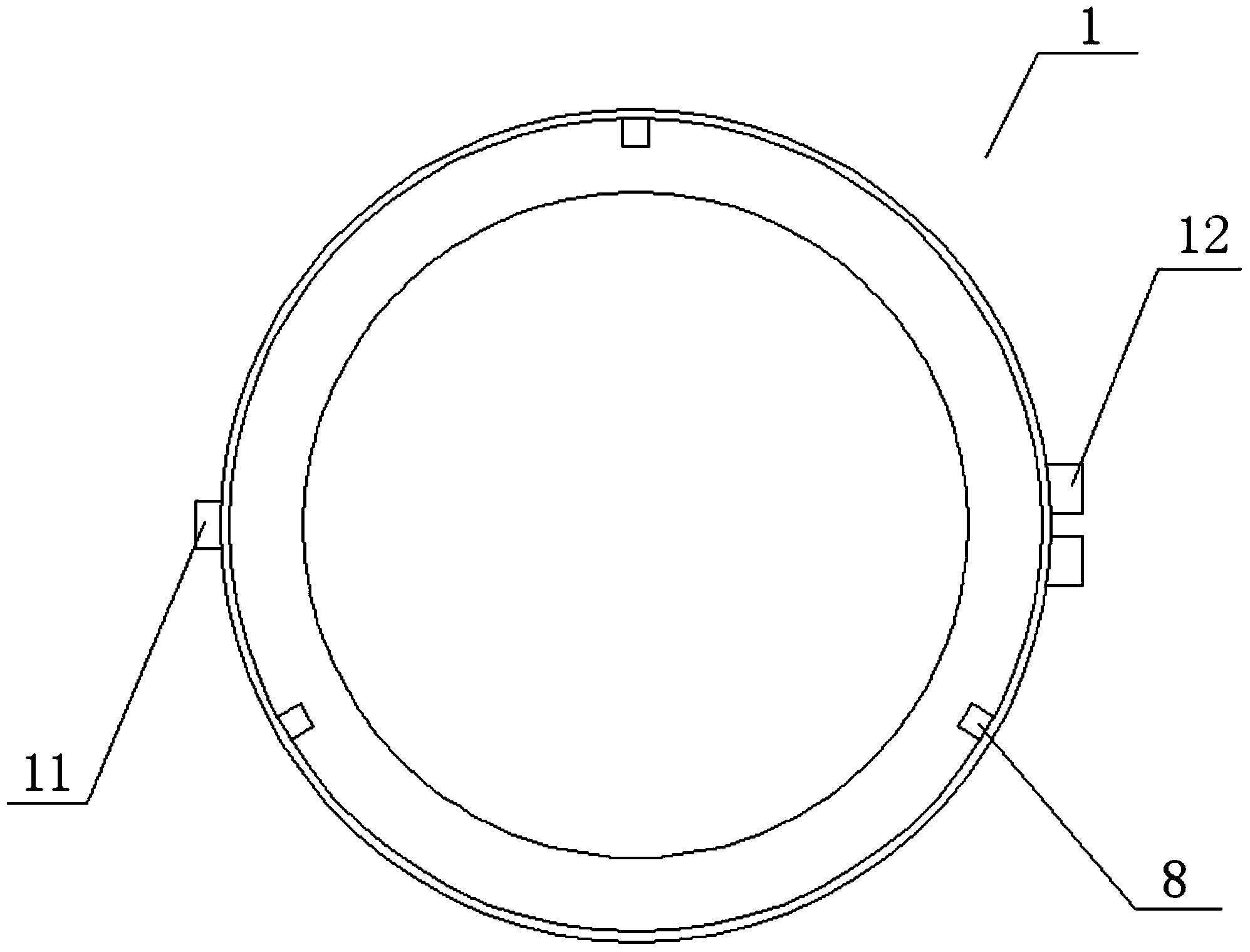
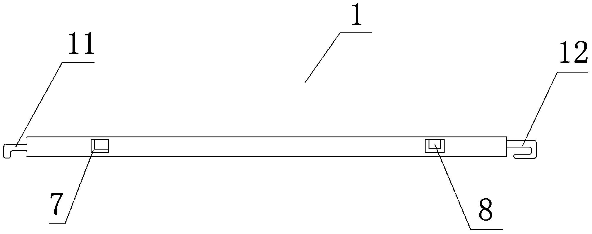
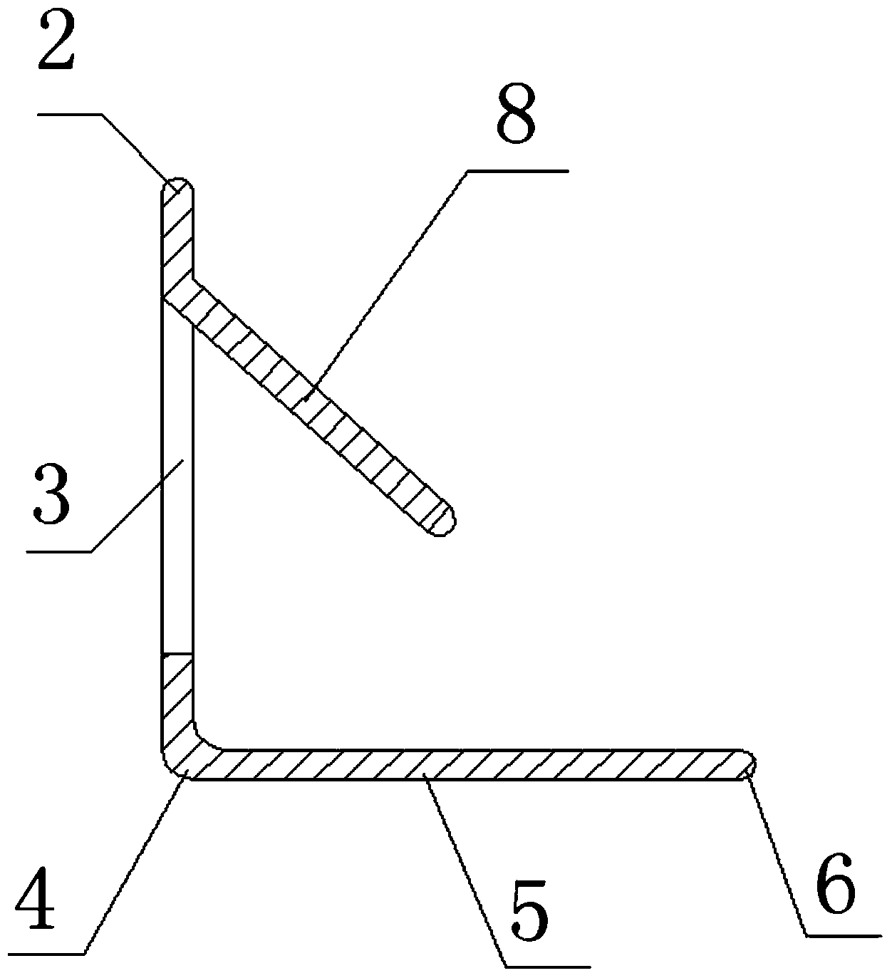
[0023] The embodiments of the present invention will be described in detail below with reference to the drawings. Such as Figure 1 to Figure 6 As shown, the first specific implementation of the present invention is a fixing ring 1 used to fix the lampshade of an industrial lighting lamp, which is cylindrical and has an "L" cross-section, which can cover the lampshade 9, and the fixing ring 1 point Is the upper semicircle 2, the vertical section 3, the arc section 4, the horizontal section 5, and the lower semicircle section 6. The upper semicircle 2 is connected to the upper end of the vertical section 3, and the lower end of the vertical section 3 is connected to one of the arc sections 4. On the side, the other side of the arc-shaped section 4 is connected to one side of the horizontal section 5, the other side of the horizontal section 5 is connected to the lower semicircle section 6, and the vertical section 3 and the horizontal section 4 are perpendicular to each other. In


PUM


Abstract

The invention discloses a fixing ring used for fixing a lamp cover of an industrial illumination lamp. The fixing ring is cylindrical and the section of the fixing ring is L-shaped; the lamp cover can be arranged in the fixing ring in a sleeving manner; the fixing ring comprises an upper semicircle part, a vertical section, an arc-shaped section, a horizontal section and a lower semicircle part; a plurality of through holes are formed in an annular face of the vertical section; the upper sides of the through holes are provided with reversed sheets which obliquely and downwards stretch into the fixing ring; the distance from the lower ends of the reversed sheets to the inner side face of the horizontal section of the fixing ring is less than the thickness of a horizontal connection section of the lamp cover and the reversed sheets are used for fixing the lamp cover; reversing hooks are further arranged on the outer sides of the fixing ring body and can be connected with a hinge arranged on a lamp holder; the lamp cover is driven by the reversing hooks to do opening-closing rotary movement relative to the lamp holder around the hinge; a backward buckling hook is further arranged on the outer side, which is opposite to the reversing hooks, of the fixing ring; the fixing ring can be connected and buckled on a hasp on the lamp holder through the backward buckling hook. The fixing ring used for fixing the lamp cover of the industrial illumination lamp is simple in structure, simple and convenient to operate and low in cost.

Description


Claims


Application Information

Patent Timeline
Owner SICHUAN LINGCHUANG BAOYAN ELECTRONICS TECH
Why Eureka
Try Eureka