Manufacturing method of plate type integrated power battery module

A technology of power battery and production method, which is applied in the direction of secondary battery manufacturing, secondary battery, multi-mode battery, etc., can solve the problems of electric vehicle development constraints, difficulty in replacement and supervision, and increase in vehicle weight, so as to facilitate long-distance Monitoring and management, long-term use without maintenance, and long cycle life

Active Publication Date: 2017-07-04
SHENZHEN HONGYUAN BODE NEW ENERGY TECH DEV
View PDF6 Cites 0 Cited by
  • Summary
  • Abstract
  • Description
  • Claims
  • Application Information

AI Technical Summary

Problems solved by technology

[0003] At present, most of the electric vehicle power batteries produced by the known production methods of electric vehicle power batteries are large in size, occupy a large spac

Method used


Image

  • Manufacturing method of plate type integrated power battery module
  • Manufacturing method of plate type integrated power battery module
  • Manufacturing method of plate type integrated power battery module

Examples


Example Embodiment

[0077] In order to further illustrate the technical means adopted by the present invention and its technical effects, the following describes in detail the preferred embodiments of the present invention and the accompanying drawings.

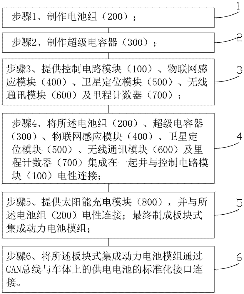
[0078] The manufacturing method of the plate-type integrated power battery module of the present invention includes the following steps:

[0079] Step 1. Make the battery pack 200.

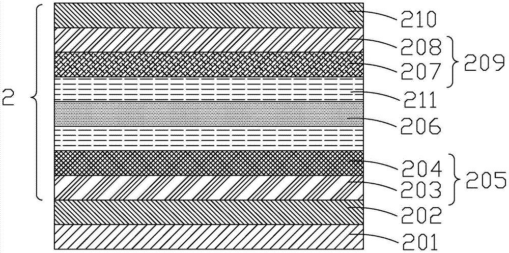
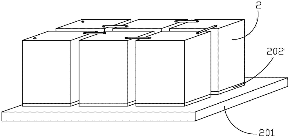
[0080] Made by figure 2 The battery cell 2 shown is composed of image 3 The steps of the battery pack 200 shown are as follows:

[0081] Step 101: Provide a flat substrate 201.

[0082] Preferably, the material of the planar substrate 201 is ceramic. In addition, metal layers are formed on both sides of the planar substrate 201 to serve as capacitors. Preferably, the metal layer is copper or aluminum. The planar substrate 201 is divided into several substrate units, and the area of ​​each substrate unit is the area required to form a battery cell. Preferably, the thickness


PUM

PropertyMeasurementUnit
Withstand voltageaaaaaaaaaa

Abstract

The invention provides a method for manufacturing a plate-type integrated power battery module, comprising the following steps: Step 1, making a battery pack (200); Step 2, making a supercapacitor (300); Step 3, providing a control circuit module (100) , Internet of Things sensing module (400), satellite positioning module (500), wireless communication module (600) and mileage counter (700); step 4, battery pack (200), supercapacitor (300), Internet of Things sensing module ( 400), the satellite positioning module (500), the wireless communication module (600) and the mileage counter (700) are integrated and electrically connected with the control circuit module (100); step 5, providing the solar charging module (800), and connecting with the battery pack (200) Electrically connect to make a block-type integrated power battery module; step 6, connect the block-type integrated power battery module to the interface of the power supply battery.

Description


Claims


Application Information

Patent Timeline
Owner SHENZHEN HONGYUAN BODE NEW ENERGY TECH DEV
Why Eureka
Try Eureka