Dryer for refuse treatment

A technology for garbage disposal and dryer, applied in the combustion method, combustion type, incinerator, etc., can solve the problems of increased energy consumption for garbage drying, unfavorable popularization of garbage disposal, etc., and achieve obvious energy saving effect and improve drying effect. , The effect of less investment in equipment

Inactive Publication Date: 2015-05-20
XIAN ALL SAFE SCI & TECH
View PDF0 Cites 0 Cited by
  • Summary
  • Abstract
  • Description
  • Claims
  • Application Information

AI Technical Summary

Benefits of technology

This new type of drier improves its performance by having more long runs between upper and lower parts than previous designs without adding extra weight or making it larger. It also considers use of an efficient heat pile instead of traditional methods like burning fuel oil at constant temperature. Overall, this design makes sure things run better while still being cost-effective compared to older options such as steam systems.

Problems solved by technology

The technical problem addressed in this patented technology relates to finding ways to dispose of excessive amounts of household or industrial wastes without causing environmental concerns such as pollution caused by burning fossil fuels that produce greenhouse gases during combustion processes.

Method used


Image

  • Dryer for refuse treatment

Examples


Embodiment Construction

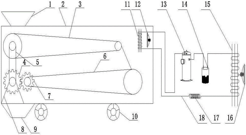
[0020] Such as figure 1 A dryer for garbage disposal is shown, which includes a rectangular shell 2 with a hollow structure and a heat pump system for raising the temperature inside the shell 2. A feed hopper 1 is provided on the top side of the shell 2, so that The bottom opening of the feed hopper 1 extends to the inside of the housing 2, and a first conveyor belt 3 for transporting garbage from left to right is arranged below the bottom opening of the feed hopper 1 inside the housing 2. The two ends of the transmission belt 3 are respectively set on the left and right transmission wheels, and the diameter of the left transmission wheel set with the first transmission belt 3 is larger than the diameter of the right transmission wheel, and it is located below the first transmission belt 3 inside the housing 2. For the second conveyor belt 6 that transports the garbage from right to left, the two ends of the second conveyor belt 6 are respectively set on the other two left and ri


PUM


Abstract

The invention discloses a dryer for refuse treatment. The dryer comprises a shell and a heat pump system used for raising the temperature inside the shell. A feeding hopper is arranged at the top of the shell. A first conveying belt is arranged below a bottom opening, inside the shell, of the feeding hopper, and the two ends of the first conveying belt are arranged on a left driving wheel and a right driving wheel in a sleeving mode respectively. A second conveying belt is arranged at the position, below the first conveying belt, inside the shell, and the two ends of the second conveying belt are arranged on another left driving wheel and another right driving wheel in a sleeving mode respectively. A gear motor is installed on the lower portion of the shell and drives the first conveying belt to move through a transmission belt, an output shaft of the gear motor is sleeved with a driving gear, and a driven gear is fixedly installed on the left driving wheel sleeved with the second conveying belt. The heat pump system comprises a closed refrigerant pipeline, and an air compressor, a gas and liquid separator, an evaporator, a throttling valve and a condenser are connected to the refrigerant pipeline. The dryer saves energy and is large in drying capacity, small in occupied area and convenient to apply and popularize.

Description


Claims


Application Information

Patent Timeline
Owner XIAN ALL SAFE SCI & TECH
Why Eureka
Try Eureka