Air-cooled thermoelectric power generation apparatus and solar thermal power generation apparatus using air-cooled thermoelectric power generation apparatus
A technology for thermal power generation and thermoelectric power generation, which is applied in the direction of using solar energy to generate mechanical power, solar thermal power generation, generators/motors, etc. Effect
- Summary
- Abstract
- Description
- Claims
- Application Information
AI Technical Summary
Problems solved by technology
Method used
Image

Examples
Embodiment 1
[0084] Hereinafter, specific examples will be further described. In the following description, the case where solar thermal energy is used is demonstrated as a method of heating a heat medium, However, As mentioned above, it is not limited to this.
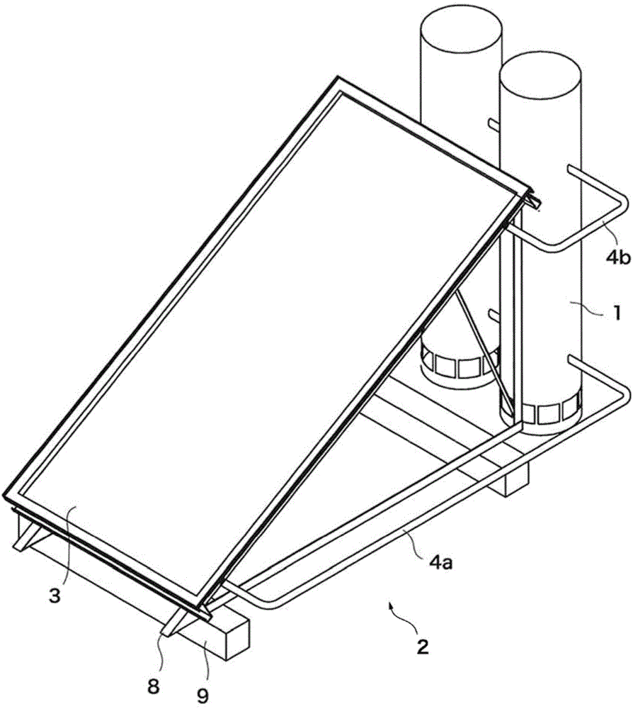
[0085] A case where the air-cooled thermoelectric power generation device 1 of the present invention is used as the solar thermal power generation device 2 will be described. The solar thermal power generation device 2 heats the heat medium by collecting heat from the sun's light energy by the solar thermal heat collection device 3 , and generates power by using the temperature difference between the two surfaces of the thermoelectric power generation element.
[0086]Since the solar thermal power generation device 2 has a plurality of embodiments depending on the configuration of each device, each embodiment will be described below. In addition, the solar thermal power generation device 2 is not limited to each of the following emb
Embodiment 2
[0124] Another example of the solar thermal power generation device 2 will be described. In Embodiment 1, the shape of the flow tube 120 is a square prism, but in this embodiment, the case where the shape of the flow tube 120' is a hexagonal prism will be described. In this case, a vertical cross-sectional view showing the vicinity of the upper part of the air-cooled thermoelectric power generation device 1' is shown in Figure 13 middle. Additionally, the Figure 13 The cross-sectional view of the β-β line is shown in Figure 14 middle. Additionally, the Figure 14 The longitudinal sectional view of the γ-γ line is shown in Figure 15 middle.
[0125] The air-cooled thermoelectric generating unit 12' in this embodiment includes a flow tube 120', a thermoelectric generating element 121, heat insulating materials 122, 123, and a cooling plate 126'. In addition, the description of parts having the same configuration as that of the air-cooled thermoelectric power generation u
Embodiment 3
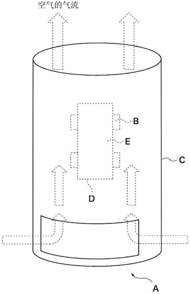
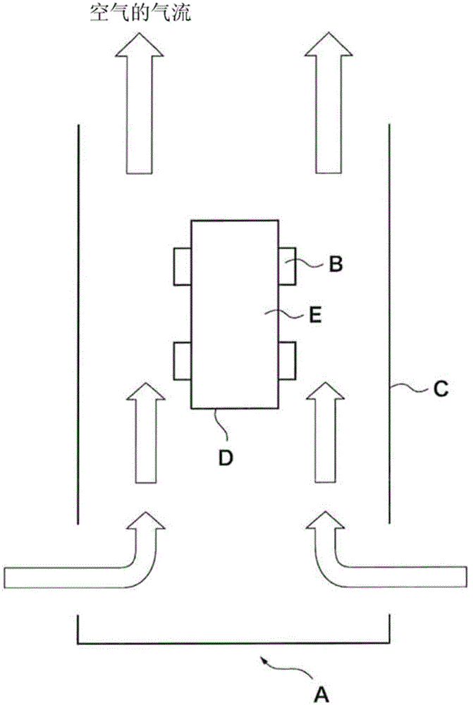
[0136] In the air-cooled thermoelectric generator 1 described above, natural air cooling is used, but for example, a cooling electric fan 128 may be provided below the air-cooled thermoelectric generator 12 to flow air from below to above. A longitudinal sectional view of the casing 11 in this case is shown in Figure 16 middle. In addition, since air can flow from above to below even when the cooling electric fan 128 is provided, the cooling electric fan 128 may be provided above the thermoelectric generation unit 12 .
[0137] In addition, instead of installing an electric cooling fan in each air-cooled thermoelectric generation unit 12 , an electric cooling fan 128 may be provided below or above the housing 11 to generate air flow inside the housing 11 .
[0138] With such a configuration, the cooling effect of the cooling fins 126 and 126' can be enhanced, so that the temperature difference of the thermoelectric power generation element 121 can be increased, leading to an im
PUM
 Abstract
Description
Claims
Application Information
 - R&D Engineer
- R&D Manager
- IP Professional
- Industry Leading Data Capabilities
- Powerful AI technology
- Patent DNA Extraction
Browse by: Latest US Patents, China's latest patents, Technical Efficacy Thesaurus, Application Domain, Technology Topic.
© 2024 PatSnap. All rights reserved.Legal|Privacy policy|Modern Slavery Act Transparency Statement|Sitemap