Connector for a compressor assembly

Active Publication Date: 2017-11-23
KONINKLJIJKE PHILIPS NV
View PDF3 Cites 2 Cited by
  • Summary
  • Abstract
  • Description
  • Claims
  • Application Information

AI Technical Summary

Benefits of technology

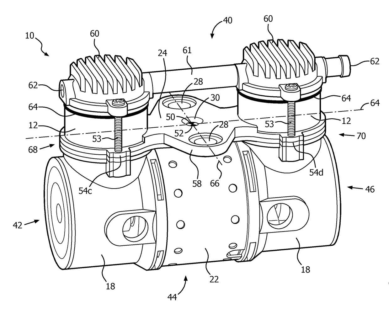
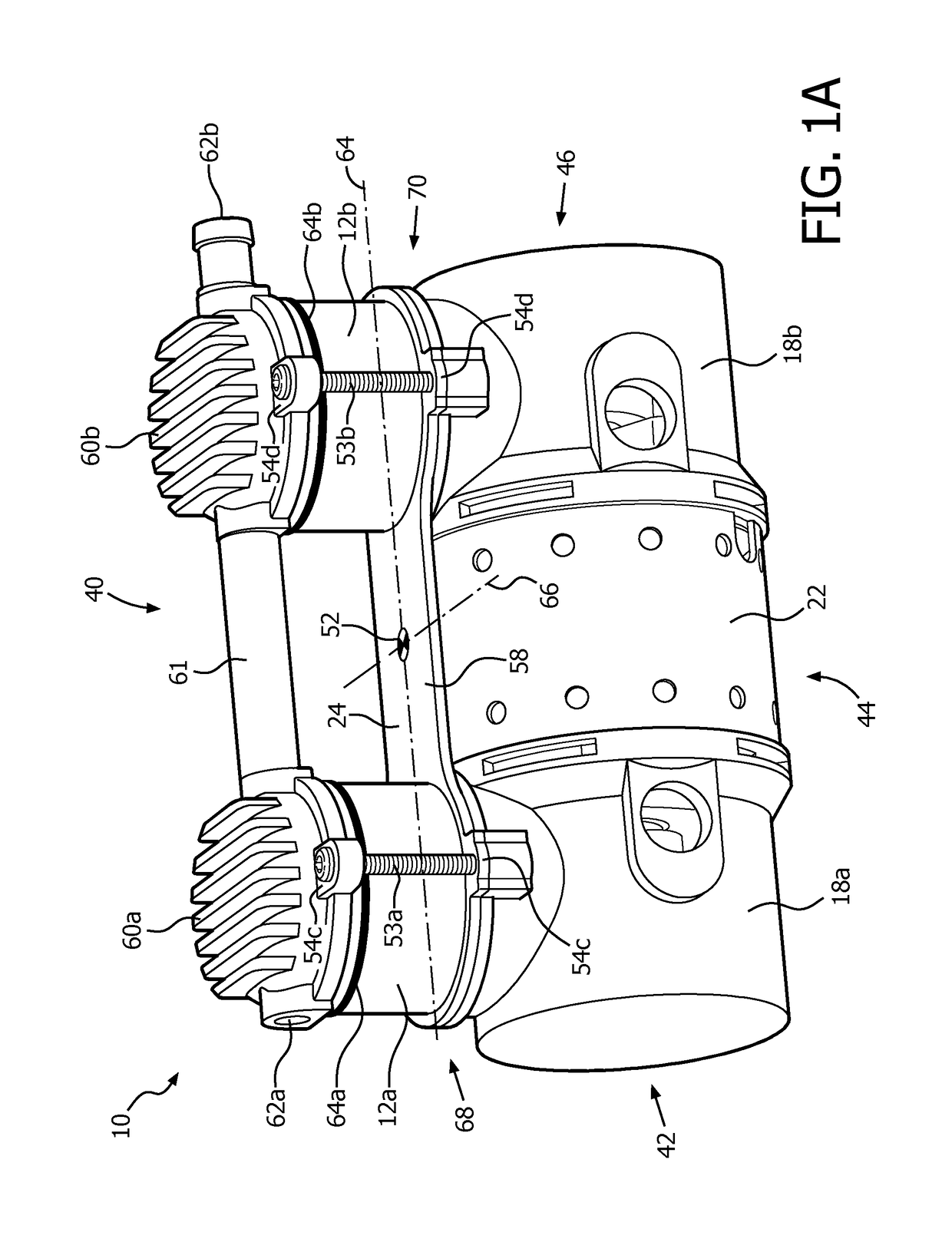
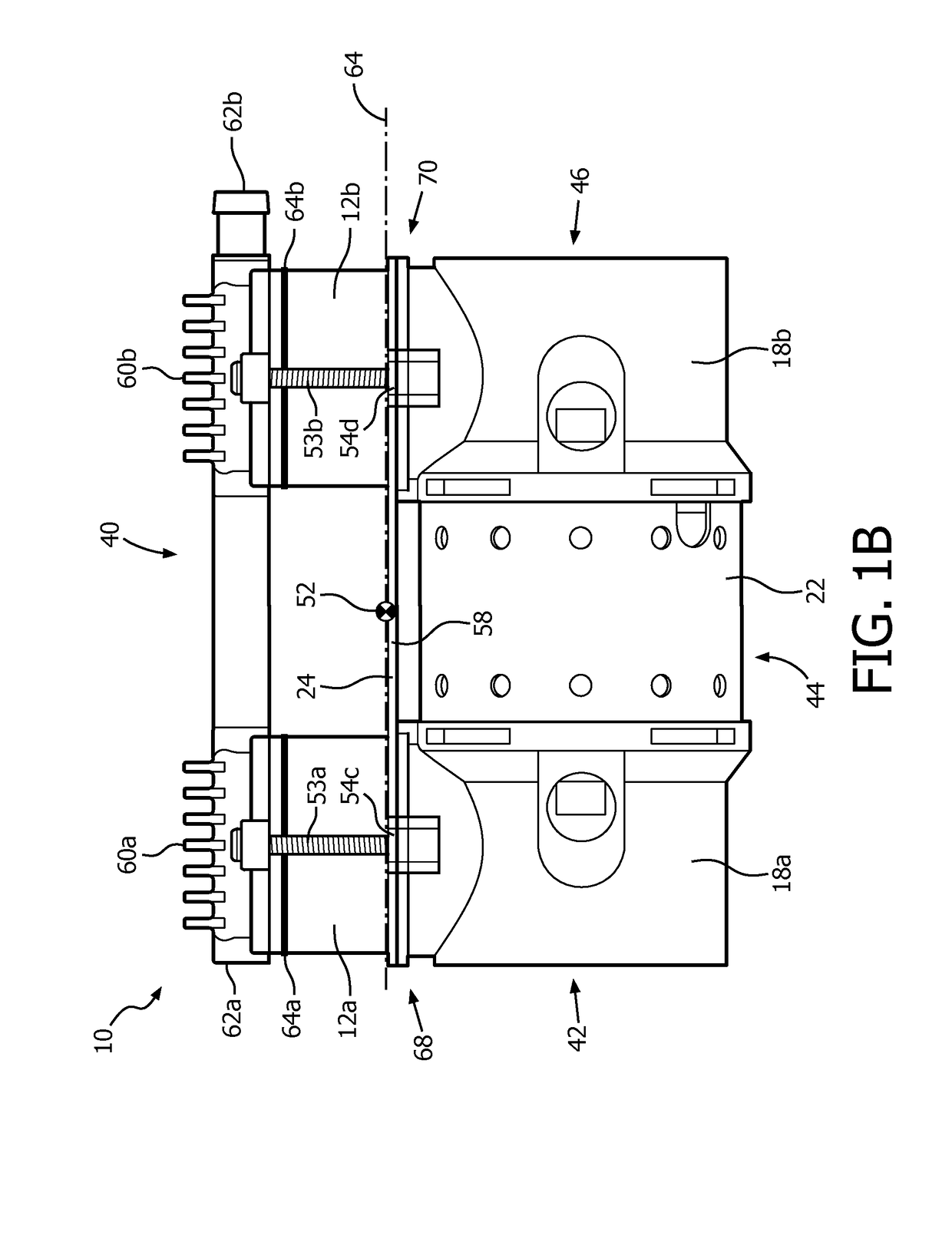
[0006]Accordingly, one or more aspects of the present disclosure relate to a compressor assembly configured to increase pressure of a fluid. The compressor assembly comprising: a first cylinder that forms a first space for compressing a fluid; a first piston housed within the first cylinder, the first piston being configured to reciprocate within the first cylinder so as to compress the fluid within the first space; a second cylinder that forms a second space for compressing the fluid that is separate from the first space; a second piston housed within the second cylinder, the second piston being configured to reciprocate within the second cylinder so as to compress the fluid within the second space; a first crank shaft housing operatively coupled with the first cylinder; a first crank shaft housed within the first crank shaft housing, the first crank shaft being configured to drive the first piston; a second c

Problems solved by technology

The cup seal flexes during movement of the piston within the cylinder and the frictional engagement creates wear along the cup seal.
This heat hastens failure of the flexible cup seal, thus limiting the life of the compressor.
This is problematic when the thermal heat fro

Method used


Image

  • Connector for a compressor assembly
  • Connector for a compressor assembly
  • Connector for a compressor assembly

Examples


Embodiment Construction

[0021]As used herein, the singular form of “a”, “an”, and “the” include plural references unless the context clearly dictates otherwise. As used herein, the statement that two or more parts or components are “coupled” shall mean that the parts are joined or operate together either directly or indirectly, i.e., through one or more intermediate parts or components, so long as a link occurs. As used herein, “directly coupled” means that two elements are directly in contact with each other. As used herein, “fixedly coupled” or “fixed” means that two components are coupled so as to move as one while maintaining a constant orientation relative to each other.

[0022]As used herein, the word “unitary” means a component is created as a single piece or unit. That is, a component that includes pieces that are created separately and then coupled together as a unit is not a “unitary” component or body. As employed herein, the statement that two or more parts or components “engage” one another shall m


PUM


Abstract

A connector (24) and method of connecting a compressor assembly (10) that increases the pressure of a fluid are described. The compressor assembly (10) includes cylinders (12a,b), crank shaft housings (18a,b), and a motor housing (22). The connector (24) is disposed between the cylinders (12a,b) and the crank shaft housing (18a,b) and configured to engage the cylinders (12a,b) such that vibration during operation of the compressor assembly is reduced through the placement of the connector (24) corresponding to a center of gravity of the compressor assembly (10). The connector may also be used by the compressor assembly as a heat sink, inlet, mount, filter, and/or to provide other functions that improve the operation of compressor assembly.

Description


Claims


Application Information

Patent Timeline
Owner KONINKLJIJKE PHILIPS NV
Why Eureka
Try Eureka