Pumping unit speed reducer shaft head sealing structure

A machine reducer and sealing structure technology, which is applied in the direction of engine sealing, mechanical equipment, engine components, etc., can solve the problems of poor sealing performance, short service life, wear, etc., achieve reliable sealing performance, improve sealing performance, and service life long effect

Inactive Publication Date: 2015-06-03
朱杏生
View PDF7 Cites 4 Cited by
  • Summary
  • Abstract
  • Description
  • Claims
  • Application Information

AI Technical Summary

Problems solved by technology

[0002] In oilfield exploitation, oil pumping unit reducers often have different degrees of oil leakage. The main parts of oil leakage are the joint surface of the upper and lower casings, the shaft head of the input shaft and output shaft, and the bearing end cover. The seal materials are mainly Felt and rectangular rubber play a sealing role by pressing the gland. The disadvantage is that the sealing performance is poor. With the prolongation of use time, the soft packing will be compressed and deformed for a long time, lose its original elasticity, and gradually wear

Method used


Image

  • Pumping unit speed reducer shaft head sealing structure

Examples


Example Embodiment

[0010] The present invention will be described below with reference to the drawings.

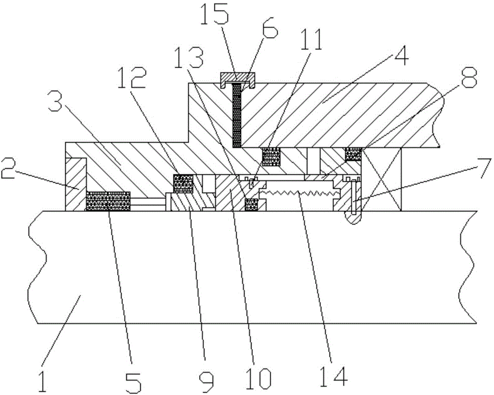
[0011] Attached figure 1 The shaft head sealing structure of the reducer of the pumping unit according to the present invention includes a shaft head 1, a gland 2, a bearing end cover 3, and a box body 4. The gland 2 and the bearing end cover 3 are directly provided with a rectangular shape A rubber ring 5, an asbestos gasket 6 is provided between the bearing end cover 3 and the box body 4, and an asbestos gasket 6 is provided between the bearing end cover 3 and the box body 4, and a sealing cover 15 is also provided; the shaft A transmission sleeve 8 is installed on the head 1 through a fixed pin 7; a static ring 9 is arranged inside the bearing end cover 3; a moving ring 10 is connected to the transmission sleeve 8; a pin 11 is installed on the moving ring 10; The stationary ring 9 and the moving ring 10 are respectively provided with a stationary ring O-shaped rubber ring 12 and a moving ring


PUM


Abstract

The invention discloses a pumping unit speed reducer shaft head sealing structure which comprises a shaft head, a gland, a bearing end cover and a box body, wherein a rectangular rubber ring is directly arranged on both the gland and the bearing end cover; an asbestos pad is arranged between the bearing end cover and the box body; a sealing cover is further arranged at the part, where the asbestos pad is arranged, between the bearing end cover and the box body; a transmission sleeve is mounted on the shaft head through a fixed pin; a fixed ring is arranged in the bearing end cover; a moving ring is arranged on and connected with the transmission sleeve; a pin is mounted on the moving ring; a fixed ring O-shaped rubber ring and a moving ring O-shaped rubber ring are respectively arranged on the fixed ring and the moving ring; and a spring is mounted between the moving ring and the transmission sleeve. By adopting the technical scheme, reliable sealing performance of the pumping unit speed reducer shaft head sealing structure is realized and the service life is long.

Description


Claims


Application Information

Patent Timeline
Owner 朱杏生
Why Eureka
Try Eureka