Vehicle locating device with high stability

A positioning device and stability technology, applied in vehicle parts, transportation and packaging, etc., can solve the problems of cumbersome production process, unstable structure, detachment of positioning column, etc., and achieve the effect of simple production process, simple structure and stable structure

Inactive Publication Date: 2015-07-29
CHENGDU RUIYI INFORMATION TECH
View PDF5 Cites 6 Cited by
  • Summary
  • Abstract
  • Description
  • Claims
  • Application Information

AI Technical Summary

Benefits of technology

This patented technology allows for better impact resistance by utilizing spring elements or rubber pillows instead of traditional methods like steel beams. It achieves this through arranging it within two supporting plate layers called horizontally supports, creating an elastic system where forces act along both vertical directions equally well. A limitation part prevents excessive movements caused by gravity when there's no load applied. Additionally, a special type of mount made of metal provides added strength without adding extra weight compared to existing structures. Overall, these technical features improve safety performance during use while maintain their overall design flexibility.

Problems solved by technology

This patented technical problem addressed in this patents relating to vehicles equipped with location devices (LID) involves improving their durability against damage caused during collisions or crashes while also enhancing their functionality for providing useful services such as navigation systems.

Method used


Image

  • Vehicle locating device with high stability

Examples


Embodiment 1

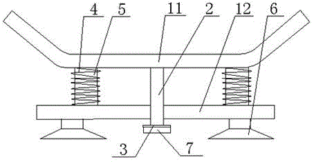
[0023] Such as figure 1 A vehicle-mounted positioning device with high stability shown includes a positioning device, an upper support plate 11 and a lower support plate 12. The upper support plate 11 includes a horizontal support plate and inclined support plates positioned at both ends of the horizontal support plate. The positioning device is fixed on the horizontal support plate of the upper support plate 11, the bottom of the upper support plate 11 is provided with a positioning column 2 perpendicular to the lower support plate 12 and one end passes through the lower support plate 12, the upper support plate 12 A shock absorber assembly is arranged between the horizontal support plate of the support plate 11 and the lower support plate 12, and the shock absorber assembly includes a spring 4 and a rubber column 5 located in the spring 4, and the two parts of the spring 4 and the rubber column 5 The ends are respectively fixed on the upper support plate 11 and the lower suppor

Embodiment 2

[0025] Such as figure 1 In the vehicle-mounted positioning device with high stability shown, in order to further improve the stability of the device, this embodiment is optimized on the basis of the above-mentioned embodiments, that is, there are at least two groups of shock-absorbing components.

Embodiment 3

[0027] Such as figure 1 In the vehicle-mounted positioning device with high stability shown in the present embodiment, an implementation is preferred on the basis of embodiment 2, that is, there are two groups of shock-absorbing assemblies.

[0028] In order to further improve the stability of the device, the positioning column 2 is located at the center of the shock absorbing assembly.

[0029] Example 3:

[0030] Such as figure 1 In the vehicle-mounted positioning device with high stability shown, in order to further improve the shock absorption effect, this embodiment is optimized on the basis of the above-mentioned embodiment, that is, the position of the limiting piece 7 adjacent to the lower support plate 12 A shock-absorbing sheet 3 is arranged on one side.

[0031] The shock-absorbing sheet 3 is a rubber sheet.


PUM


Abstract

The invention discloses a vehicle locating device with high stability. The device comprises a locating device, an upper support plate and a lower support plate, wherein the upper support plate comprises a horizontal support plate and two inclined support plates which are respectively arranged at the two ends of the horizontal support plate; the locating device is fixed on the horizontal support plate of the upper support plate; a locating column which is vertical to the lower support plate is arranged at the bottom of the upper support plate, and one end of the locating column passes through the lower support plate; a shock absorption component is arranged between the horizontal support plate of the upper support plate and the lower support plate; the shock absorption component comprises a spring and a rubber column arranged in the spring; the two ends of each of the spring and the rubber column are respectively fixed on the upper support plate and the lower support plate; the locating column is provided with a limiting piece at the end passing through the lower support plate; a rubber absorption cup is arranged at the bottom of the lower support plate. The vehicle locating device is simple in structure and easy to manufacture; the locating column does not easily fall off, so that the structure is stable.

Description


Claims


Application Information

Patent Timeline
Owner CHENGDU RUIYI INFORMATION TECH
Why Eureka
Try Eureka