A centrifugal microfluidic emulsification device and method thereof

A microfluidic and microfluidic chip technology, which is applied in chemical instruments and methods, mixing methods, dissolution, etc., can solve the problems of complex structure of microfluidic equipment and low emulsification efficiency, and solve the problems of complex structure of equipment and emulsification quality. Good, the effect of improving economic benefits

Active Publication Date: 2018-07-06
SOUTH CHINA NORMAL UNIVERSITY +2
View PDF6 Cites 0 Cited by
  • Summary
  • Abstract
  • Description
  • Claims
  • Application Information

AI Technical Summary

Problems solved by technology

[0006] In order to overcome the deficiencies of the existing technology, the present invention provides a centrifugal microfluidic emulsification devic

Method used


Image

  • A centrifugal microfluidic emulsification device and method thereof
  • A centrifugal microfluidic emulsification device and method thereof

Examples


Embodiment Construction

[0017] The idea, specific structure and technical effects of the present invention will be clearly and completely described below in conjunction with the embodiments and accompanying drawings, so as to fully understand the purpose, features and effects of the present invention. Apparently, the described embodiments are only some of the embodiments of the present invention, rather than all of them. Based on the embodiments of the present invention, other embodiments obtained by those skilled in the art without creative efforts belong to The protection scope of the present invention. In addition, all the connection / connection relationships involved in the patent do not simply refer to the direct connection of components, but mean that a better connection structure can be formed by adding or reducing connection accessories according to specific implementation conditions. The various technical features in the invention can be combined interactively on the premise of not contradicti


PUM


Abstract

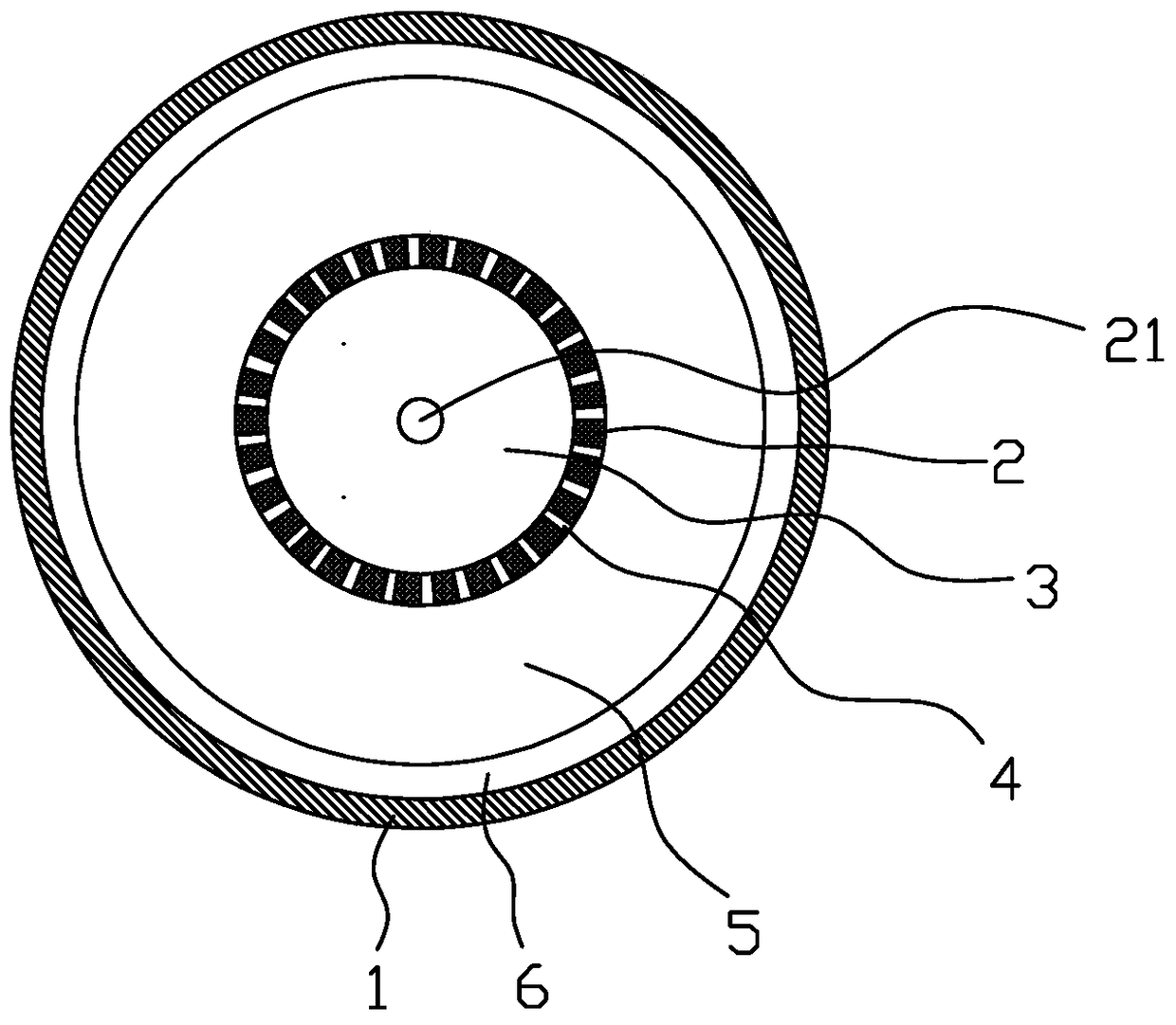
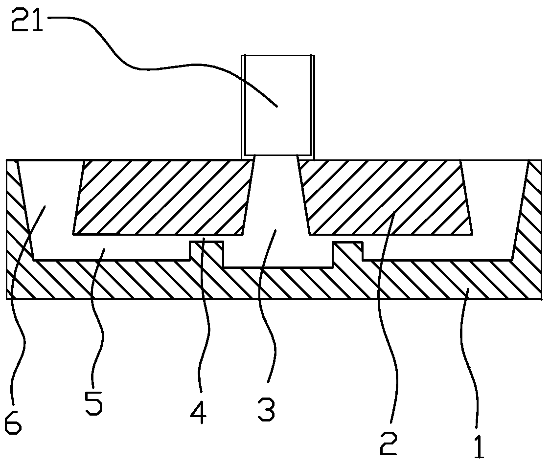
The invention discloses a centrifugal microfluidic emulsification device and a method thereof, wherein the centrifugal microfluidic emulsification device comprises a microfluidic shell, a microfluidic chip built in the inner cavity of the microfluidic shell, and a drive unit. The power device in which the microfluidic chip rotates in the inner cavity of the microfluidic shell, the microfluidic chip is a circular disc body, and an internal phase storage pool is arranged inside, and an internal phase inlet is opened on the upper part of the microfluidic chip And the inner phase inlet is connected with the inner phase storage pool, and a plurality of microchannels are evenly opened between the inner phase storage pool in the microfluidic chip and the outer wall of the microfluidic chip circumference, and the outer side of the microfluidic chip An external phase storage pool and a collection pool for collecting emulsions are arranged between the wall and the inner wall of the microfluidic housing. The microchannels provided on the microfluidic chip are single-layer or multi-layer. One or more microfluidic chips are arranged in the inner cavity. The centrifugal microfluidic emulsification device and method thereof have the advantages of high emulsification efficiency, stable emulsification quality, good emulsification quality, simple equipment structure, low production cost and other advantages that the prior art does not possess.

Description


Claims


Application Information

Patent Timeline
Owner SOUTH CHINA NORMAL UNIVERSITY
Why Eureka
Try Eureka