Independent multichannel immunofluorescence microfluidic chip and immunofluorescence detection method

A microfluidic chip and immunofluorescence technology, applied in the direction of fluorescence/phosphorescence, measuring devices, instruments, etc., can solve the problems of unstable detection results, signal crosstalk, and limit the application range of chips, so as to improve detection accuracy and efficiency, reduce cost effect

Pending Publication Date: 2021-02-02
苏州含光微纳科技有限公司
View PDF0 Cites 1 Cited by
  • Summary
  • Abstract
  • Description
  • Claims
  • Application Information

AI Technical Summary

Problems solved by technology

[0005] However, the existing immune microfluidic chips all use a single-channel liquid-feeding reaction, and there is a problem of signal crosstalk when multiple items are tested, which limits the application range of the chip.
The existing multi-channel multi-target blood im

Method used


Image

  • Independent multichannel immunofluorescence microfluidic chip and immunofluorescence detection method
  • Independent multichannel immunofluorescence microfluidic chip and immunofluorescence detection method
  • Independent multichannel immunofluorescence microfluidic chip and immunofluorescence detection method

Examples


Embodiment Construction

[0028] The present invention will be described in further detail below through specific embodiments and accompanying drawings.

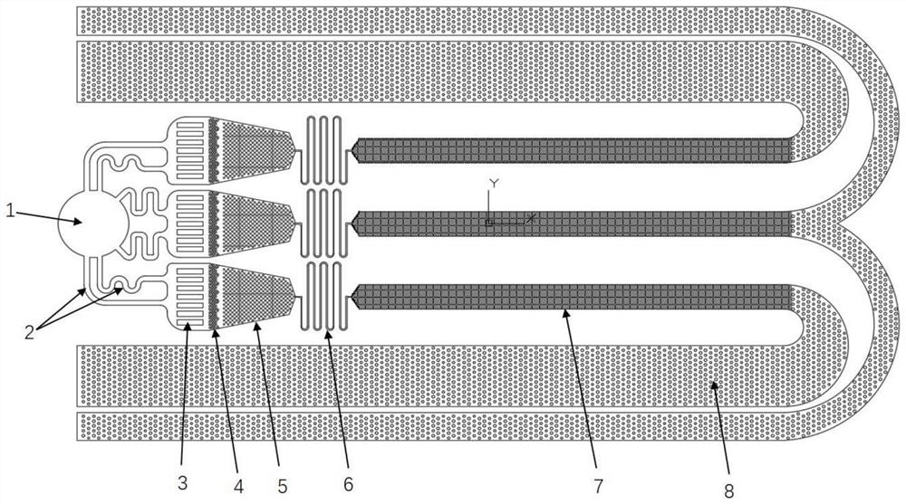
[0029] figure 1 It is a schematic diagram of the structure of the independent multi-channel immunofluorescence microfluidic chip of this embodiment, which contains three independent channels. In other embodiments, there may also be two or more than three independent channels, that is, the number of channels is at least two.

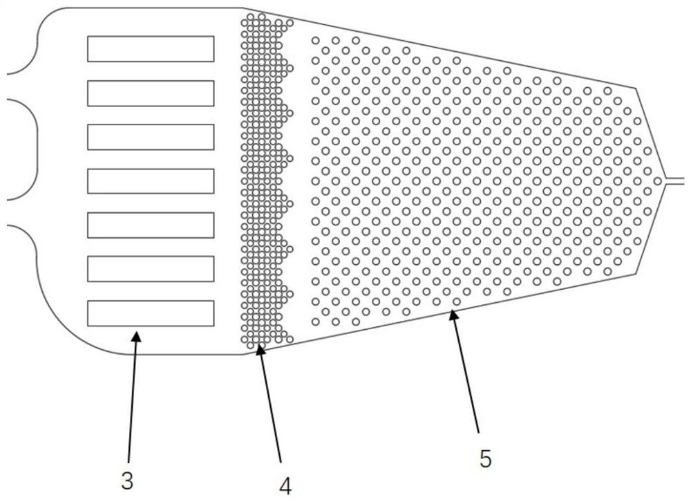
[0030] figure 1 In , the liquid inlet 1 is used to put the sample. Equal distribution channel 2 is used to realize precise liquid distribution. The purpose of using multiple curved pipes is to make the flow resistance of each channel consistent. The filter area 3 is used for filtering impurities in the sample. The buffer zone 4 is used to realize the buffering of the liquid, so that the liquid goes hand in hand. The fluorescent coating area 5 is used for the immobilization of fluorescent reagents. The time control valve 6 ad


PUM


Abstract

The invention relates to an independent multichannel immunofluorescence microfluidic chip and an immunofluorescence detection method. The independent multi-channel immunofluorescence microfluidic chipcomprises at least two independent channels, each channel comprises an equivalent uniform flow channel, a filtering area, a buffer area, a fluorescence coating area, a time control valve, a detectionarea and a waste liquid area which are connected in sequence, and the equivalent uniform flow channels of all the channels are connected with the same liquid inlet. According to the independent multi-channel immunofluorescence microfluidic chip, liquid is equally divided in the sample feeding stage, different channels have independent fluorescence antibody coating areas, space-time valves and independent waste liquid areas, and the problem that different detection items may cause mutual interference is solved; each independent channel can integrate a plurality of detection items which do notinterfere with one another, so that the detection precision and efficiency are improved and the cost is reduced while high flux is realized.

Description


Claims


Application Information

Patent Timeline
Owner 苏州含光微纳科技有限公司
Why Eureka
Try Eureka