Device for controlling liquid to flow directionally under heating condition in pipeline of micro-fluidic chip

A microfluidic chip and directional flow technology, applied in fluid controllers, heating or cooling equipment, laboratory containers, etc., can solve the problems of liquid drive technology limitations, large equipment quality and volume, and high cost of pumping technology

Active Publication Date: 2022-02-01
BEIJING INSTITUTE OF TECHNOLOGYGY
View PDF32 Cites 0 Cited by
  • Summary
  • Abstract
  • Description
  • Claims
  • Application Information

AI Technical Summary

Benefits of technology

This patented technology describes an apparatus for controlling the movement of fluids within a small space called a microchip canal system. It uses thermal energy from external sources like electricity or gas to achieve precise temperature changes on different parts inside the tiny passageway through which liquor flows. These temperatures affect how it moves along its length, allowing accurate analysis of the velocity and location at each part's level. Additionally, these techniques allow for more efficient coolant usage compared to traditional ways such as water baths. Overall, they provide technical means for efficiently managing and manipulating minute amounts of material in various industries including biology researchers.

Problems solved by technology

This patents describes various technical problem addressed in these inventions: how efficiently prepare and adjust small parts (such as fluids) from their environment while maintaining precise temperatures within them without requiring expensive machining tools like thermal chambers; how to effectively cool down liquids inside tiny channels made up of plastic tubes filled with water under controlled conditions through specific techniques called thermotropic gelators.

Method used


Image

  • Device for controlling liquid to flow directionally under heating condition in pipeline of micro-fluidic chip
  • Device for controlling liquid to flow directionally under heating condition in pipeline of micro-fluidic chip
  • Device for controlling liquid to flow directionally under heating condition in pipeline of micro-fluidic chip

Examples


Embodiment 1

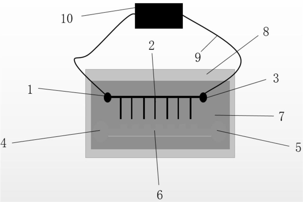
[0028] The manufacturing method of the device for controlling the directional flow of liquid by the internal heating conditions of the pipeline of the microfluidic chip disclosed in this embodiment is as follows:

[0029] Step 1: Preparation of the microfluidic chip.

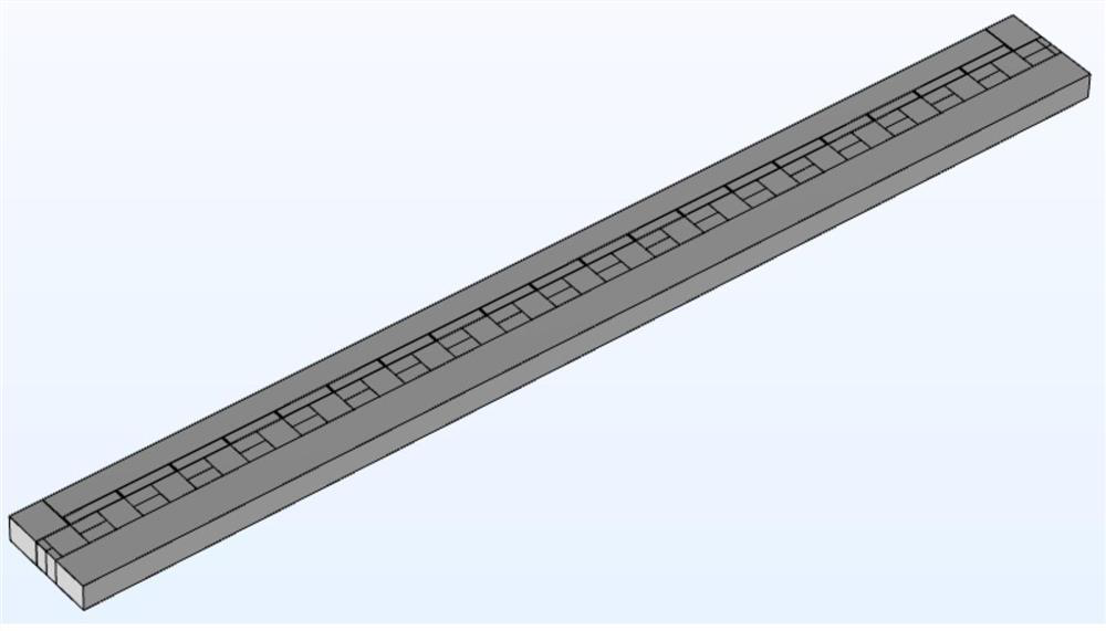
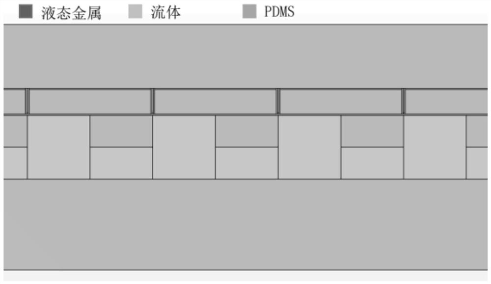
[0030] According to the biochemical reaction at the micro-nano scale to provide the reaction environment requirements, the structure of the pipeline in the microfluidic chip is designed in AutoCAD and other image design software, so that it has periodic changes. Then, according to the design drawing, the mask required by the soft lithography technology is manufactured, and the silicon wafer containing the pipeline design is manufactured through the soft lithography technology. By way of reverse molding, the pattern of the silicon wafer is printed to become a PDMS pipe, which is then cut and bonded to a glass plate using plasma processing technology to obtain a microfluidic chip with the required structure.

[0031


PUM


Abstract

The invention discloses a device for controlling liquid to flow directionally according to heating conditions in a pipeline of a micro-fluidic chip, and belongs to the field of controlling liquid to flow directionally by the micro-fluidic chip. The device comprises a micro-fluidic chip and a heating device, wherein the heating power supply is used for heating the heating micro-pipeline in the chip, and the temperature in the chip micro-fluid pipeline is controlled by adjusting the voltage, so that the temperature of the wall surface of the heating pipeline is distributed in a preset space, namely, the flow field and the temperature of the micro-fluid pipeline in the micro-fluid chip can be effectively controlled. On the basis, the geometric position structures of the heating pipeline and the microfluid pipeline are adjusted and limited, the heating pipeline and the microfluid pipeline are both of a periodic geometric structure, the phase difference between the central positions of the widest flow channels of the heating pipeline and the microfluid pipeline is pi/2, then flowing of liquid in the microfluid pipeline is adjusted and controlled, and directional flowing of the liquid is controlled. The invention can be used for temperature control of single cell scale (i.e. Micron scale).

Description


Claims


Application Information

Patent Timeline
Owner BEIJING INSTITUTE OF TECHNOLOGYGY
Why Eureka
Try Eureka