Microscope base milling fixture

A fixture and mirror base technology, which is applied in the field of mechanical processing, can solve the problems of low production efficiency and achieve the effects of high production efficiency, simple clamping, and accurate clamping and positioning

Active Publication Date: 2015-11-04
WUZHOU OKA OPTICAL INSTR
View PDF6 Cites 1 Cited by
  • Summary
  • Abstract
  • Description
  • Claims
  • Application Information

AI Technical Summary

Benefits of technology

This patented technology allows for efficient use of space during manufacturing processes by attaching different components together without requiring multiple steps or tools like screws. Additionally, it provides precise alignment when fitting these parts into place while ensuring proper assembly results.

Problems solved by technology

This patented describes how it works for both microscopes that use different types of lenses like prismatic glass plates (PV) and liquid crystal displays (LCD). However, these techniques require specialized tools such as optical filters and reflectors. Additionally, when working with other components within this system, they may also be needed separately due to their unique shapes.

Method used


Image

  • Microscope base milling fixture
  • Microscope base milling fixture
  • Microscope base milling fixture

Examples


Embodiment 1

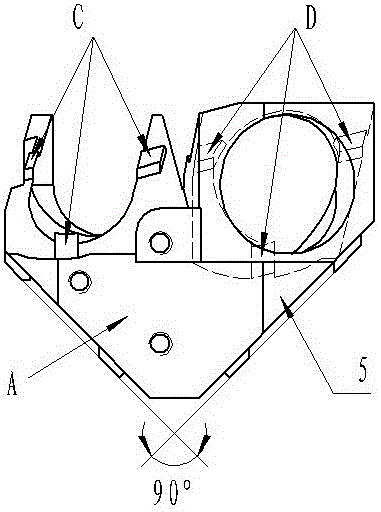
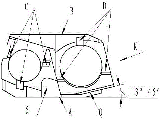
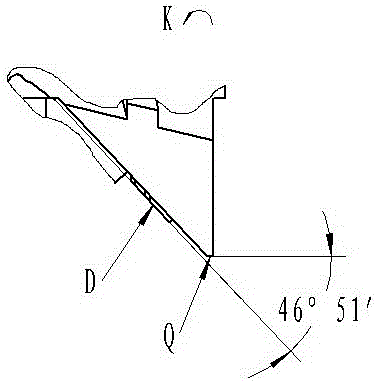
[0026] Such as Figure 7 , Figure 8 , Figure 9 The shown mirror base milling fixture includes a base 1, the base 1 is provided with a positioning slant block 1-2 and two mounting base plates 1-1 respectively connecting the two ends of the positioning slanting block 1-2, and the mounting base plate 1-1 There is a mounting groove on the top, and the positioning inclined block 1-2 has a positioning surface that forms an angle γ with its bottom surface, and the angle γ is 46°33′, such as Figure 10 , Figure 11 , Figure 12 As shown; two V-shaped supporting blocks 2 symmetrically arranged are installed on the positioning surface by bolts, and the angle between the V-shaped working surfaces of the V-shaped supporting blocks 2 is 90 degrees, as Figure 13 Shown; The V-shaped openings of the two V-shaped supporting blocks 2 are facing the high side of the positioning inclined block 1-2 and are inclined to the two outer ends respectively, the angle between the V-shaped working surf

Embodiment 2

[0029] The difference between this embodiment and Embodiment 1 lies in that the included angle γ is 46°35′, and the included angle θ is 26°21′. All the other technical features are the same as in Embodiment 1.


PUM


Abstract

The invention discloses a microscope base milling fixture and relates to the technical field of machining. The microscope base milling fixture comprises a base. The microscope base milling fixture comprises a base. The base is provided with a locating tapered block and mounting bottom plates connected with the two ends of the locating tapered block respectively. The locating tapered block is provided with a locating surface, and an included angle gamma is formed between the locating surface and the bottom surface of the locating tapered block. Two V-shaped supporting blocks are symmetrically arranged on the locating surface. The V-shaped openings of the two V-shaped supporting blocks face the high side of the locating tapered block and incline towards the two ends of the locating tapered block. The angular bisectors of the included angles of the V-shaped working faces of the two V-shaped supporting blocks intersect to form an included angle theta. A pressing plate extending to the V-shaped opening of each V-shaped supporting block is arranged on the V-shaped supporting block through a bolt. Compared with the prior art, by adopting the microscope base milling fixture, a first microscope base and a second microscope base can be clamped and machined at the same time, clamping is easy, and the production efficiency is high.

Description


Claims


Application Information

Patent Timeline
Owner WUZHOU OKA OPTICAL INSTR
Why Eureka
Try Eureka