Annular welding seam detection device with indication control function

A technology for annular welds and detection devices, applied in the direction of using sound waves/ultrasonic waves/infrasonic waves to analyze solids, etc., can solve problems such as unreliable improvement, lack of detection devices, and low efficiency, so as to achieve suitable promotion and use, simplify management, and avoid later stages classification effect

Inactive Publication Date: 2016-02-03
陈卫
View PDF0 Cites 0 Cited by
  • Summary
  • Abstract
  • Description
  • Claims
  • Application Information

AI Technical Summary

Problems solved by technology

The welded workpiece generally needs to be inspected on the welded part, for such as figure 1 The steel ring 1 in the steel ring still lacks a dedicated detection device at present, a

Method used


Image

  • Annular welding seam detection device with indication control function

Examples


Example Embodiment

[0010] The specific embodiments of the present invention will be further described below in conjunction with the accompanying drawings.

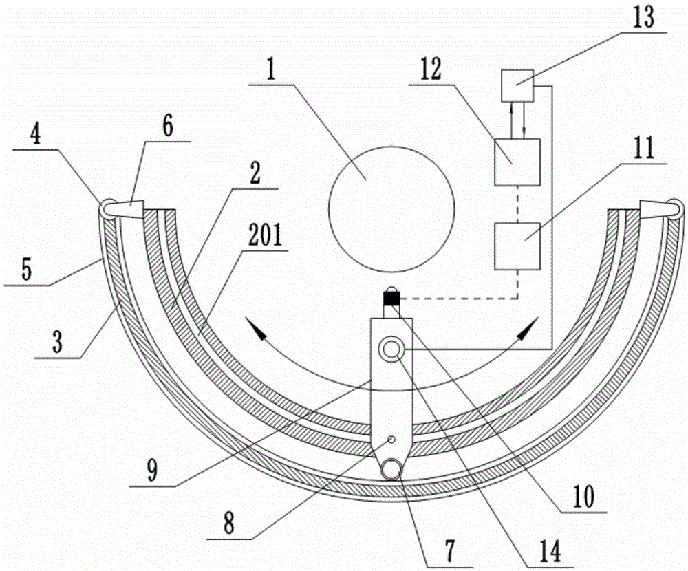
[0011] Such as figure 1 As shown, in the circular weld detection device with indicator control of this embodiment, the steel ring 1 is placed in an arc-shaped guide device, and a weld detection head 9 is slidably installed in the arc-shaped guide device, and the weld detection head 9 faces the steel ring 1; The arc guide device includes an inner arc guide plate 2 and an outer arc drive plate 3 set inside and outside. The inner arc guide plate 2 is provided with an arc guide groove 201, and both ends of the outer arc drive plate 3 pass through the ends The gear 4 is equipped with a rack 5, and the end gear 4 is connected to the inner arc guide plate 2 through a bracket 6; the outer end of the weld inspection head 9 is equipped with a guide gear 7 and a guide shaft 8, and a guide gear 7 and a rack 5 Engaged, the guide shaft 8 is fitted in the arc-s


PUM


Abstract

The invention relates to an annular welding seam detection device with an indication control function. A steel ring is placed in an arch-shaped guiding device; a welding seam detection head is mounted in the arc-shaped guiding device in a sliding manner; the welding seam detection head faces towards the steel ring; the arc-shaped guiding device comprises an inner arc-shaped guide plate and an outer arc-shaped driving plate which are arranged inside and outside; an arc-shaped guide groove is formed in the inner arc-shaped guide plate; a rack is at the two ends of the outer arc-shaped driving plate through end gears; the end gears are connected with the inner arc-shaped guide plate through brackets; a guide gear and a guide shaft are mounted at the outer end of the welding seam detection head; the guide gear is meshed with the rack; the guide shaft is mounted in the arc-shaped guide groove in a matching manner; an ultrasonic detector is mounted at the end part of the welding seam detection head; the ultrasonic detector is connected with a control center through a data processor; a comparison feedback module is arranged in the control center and feeds back comparison results to the control center; the control center controls an indicating lamp on the welding seam detection head according to the comparison results.

Description


Claims


Application Information

Patent Timeline
Owner 陈卫
Why Eureka
Try Eureka