Printed circuit board (PCB) printing device and method

A technology for printing devices and substrates, applied in printing devices, printing, typewriters, etc., to achieve the effect of flexible PCB printing

Active Publication Date: 2016-02-17
台州市吉吉知识产权运营有限公司
View PDF6 Cites 2 Cited by
  • Summary
  • Abstract
  • Description
  • Claims
  • Application Information

AI Technical Summary

Benefits of technology

This patented technology describes how a computerized printer uses special materials called circuits that connect electronic components together through conductive paths (wires). These connections allow for precise placement of these materials onto printed boards during manufacturing processes. By controlling this process based upon specific instructions from the user's equipment, it allows for more flexible and accurate production techniques.

Problems solved by technology

The technical problem addressed in this patented text relates how accurately and efficiently print circuitry on printed circuitboards (PCs).

Method used


Image

  • Printed circuit board (PCB) printing device and method
  • Printed circuit board (PCB) printing device and method
  • Printed circuit board (PCB) printing device and method

Examples


Embodiment Construction

[0032] Embodiments of the present invention are described below through specific examples, and those skilled in the art can easily understand other advantages and effects of the present invention from the content disclosed in this specification. The present invention can also be implemented or applied through other different specific implementation modes, and various modifications or changes can be made to the details in this specification based on different viewpoints and applications without departing from the spirit of the present invention. It should be noted that, in the case of no conflict, the following embodiments and features in the embodiments can be combined with each other.

[0033] It should be noted that the diagrams provided in the following embodiments are only schematically illustrating the basic ideas of the present invention, and only the components related to the present invention are shown in the diagrams rather than the number, shape and number of components


PUM


Abstract

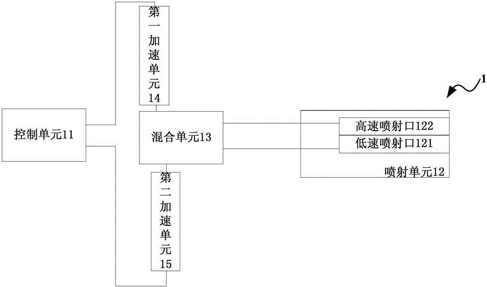
The invention provides a printed circuit board (PCB) printing device and method. The PCB printing device comprises a control unit, a spraying unit electrically connected with the control unit, a mixing unit, a first accelerating unit and a second accelerating unit. The spraying unit is provided with a low-speed spraying nozzle corresponding to the first accelerating unit and a high-speed spraying nozzle corresponding to the second accelerating unit. The control unit is used for sending a control command to the first accelerating unit so that the first accelerating unit can accelerate mixed materials in the mixing unit and spray the mixed materials onto a PCB substrate through the low-speed spraying nozzle. Or, the control unit is used for sending the control command to the second accelerating unit so that the second accelerating unit can accelerate the mixed materials in the mixing unit and spray the mixed materials onto the PCB substrate through the high-speed spraying nozzle. By means of the PCB printing device and method, the accuracy of PCB printing can be controlled precisely; in addition, the low-speed spraying nozzle and the high-speed spraying nozzle are adopted by the spraying unit, different properties of the two spraying nozzles can be effectively utilized, and PCB printing can be conducted flexibly.

Description


Claims


Application Information

Patent Timeline
Owner 台州市吉吉知识产权运营有限公司
Why Eureka
Try Eureka