Process equipment for manufacturing aluminum alloy cable insulator and sheath

A technology of cable insulation and preparation process, which is applied in the direction of conductor/cable insulation, cable/conductor manufacturing, circuit, etc. It can solve the problems of high installation requirements, reversed and scratched wires, large wires, etc., and achieve smooth surface and good concentricity Effect

Active Publication Date: 2016-02-24
安徽省惠尔电气有限公司
View PDF6 Cites 1 Cited by
  • Summary
  • Abstract
  • Description
  • Claims
  • Application Information

AI Technical Summary

Problems solved by technology

The insulation is extruded, and the sheath is extruded. In this extrusion method, after the insulation is extruded, there is gas on the surface, and the gas is not volatilized and directly enters the sheath for extrusion, which will cause obvious gaps between the insulation and the sheath. At the same time, this extrusion method has high requirements for the installation of the equipment. It is necessary to keep the insulated wire core and the sheath head on the same line, otherwise the insulation will be in a soft state without cooling, and the insulation will be damaged when it passes through the sheath mould. Scratched or scratched, and the speed of the production line is also limited by the distance between the two heads of the insulation and she

Method used


Image

  • Process equipment for manufacturing aluminum alloy cable insulator and sheath
  • Process equipment for manufacturing aluminum alloy cable insulator and sheath
  • Process equipment for manufacturing aluminum alloy cable insulator and sheath

Examples


Embodiment Construction

[0019] The present invention will be further described below in conjunction with accompanying drawing:

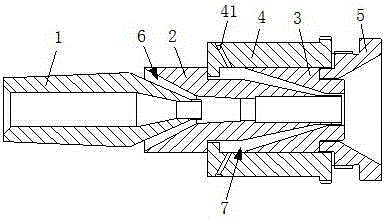
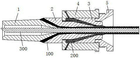
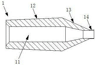
[0020] Such as figure 1 , figure 2 The shown one kind of aluminum alloy cable insulation and sheath preparation process equipment includes the inner mold 1, the middle mold 2 and the outer mold 3 which are fitted in sequence. The fitting here means that the rear part of the inner mold is located in the inner cavity of the middle mold The front part of the middle mold, the rear part of the middle mold is located in the inner cavity of the outer mold, the outer mold 3 is provided with a sheath shunt 4, the tail end of the outer mold 3 is provided with a die cover 5, and the outer wall of the inner mold 1 and the middle mold 2 A first annular passage 6 for injection of insulating material 100 is formed between the inner walls of the inner mold 2, a second annular passage 7 for injection of sheath material 200 is formed between the outer wall of the middle mold 2 and the inner w


PUM


Abstract

The invention relates to process equipment for manufacturing an aluminum alloy cable insulator and a sheath. The process equipment comprises an inner mold, a middle mold and an outer mold which are joggled in sequence, wherein the outer mold is provided with a sheath shunt, a pressing mold cover is arranged at the tail end of the outer mold, a first annular passage for injecting an insulating material is formed between the outer wall of the inner mold and the inner wall of the middle mold, a second annular passage for injecting a sheath material is formed between the outer wall of the middle mold and the inner wall of the outer mold, the sheath shunt is provided with an injection hole communicated with the second annular passage, and a conductor enters from the inner cavity of the inner mold, is matched with the insulating material to form an insulating layer when advancing to the inner cavity of the middle mold and is matched with the sheath material to form a sheath layer when advancing to the inner cavity of the outer mold. According to the technical solution, the conductor is subjected to extrusion when the insulating layer is formed and tube extrusion when the sheath layer is formed, thus realizing single extrusion of the high-temperature sheath material and the low-temperature insulating material; moreover, the insulator and the sheath have smooth surfaces and good concentricity, and the process equipment can realize high-speed continuous production.

Description


Claims


Application Information

Patent Timeline
Owner 安徽省惠尔电气有限公司
Why Eureka
Try Eureka