Adsorption device

An adsorption device and adsorbent technology, which is applied in the field of gas separation equipment, can solve the problems that the adsorption tower is not equipped with a screen opening, the distributor is unreasonably set, and the adsorbent cannot be replaced, so as to reduce energy consumption, improve utilization rate, The effect of extending the service life

Inactive Publication Date: 2016-04-20
王晓晓
View PDF0 Cites 6 Cited by
  • Summary
  • Abstract
  • Description
  • Claims
  • Application Information

AI Technical Summary

Benefits of technology

This technology helps improve the efficiency of an absorbing material used for removing harmful gases from exhaust streams effectively without requiring too much time or effort on maintenance tasks. It achieves this through uniformly distributing incoming airflow over multiple small spaces within its structure that reduces the amount needed compared with traditional methods like beds made up entirely of absorbents alone.

Problems solved by technology

This patented technology uses packing columns for separating different types of gasses like nitrogen (N2) from other substances called impurities during production processes. However due to poor distribution efficiency caused by incorrect placement of an adapter plate on certain parts of the column, it can cause issues when trying to separate specific components within these gases without losing their effectiveness over time. Additionally, current methods involve replacing spent absorbents after they have been effective enough, which requires significant maintenance costs compared to regular replacement.

Method used


Image

  • Adsorption device

Examples


Embodiment Construction

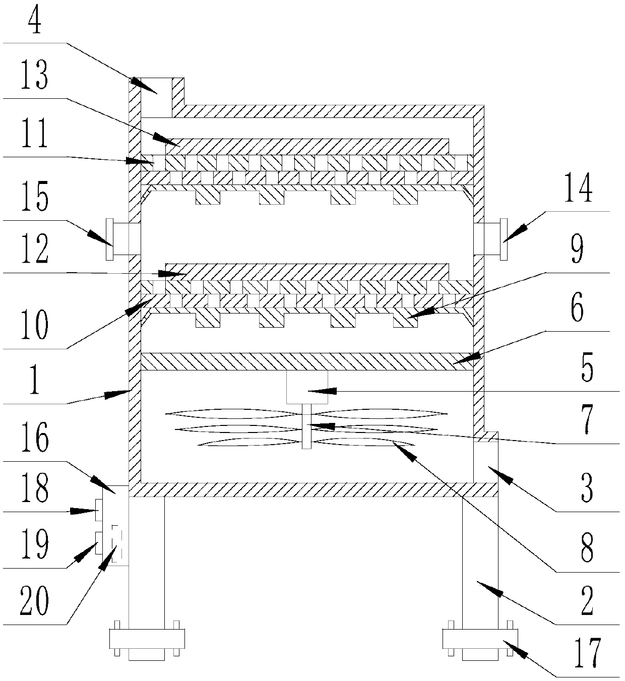
[0017] The present invention is specifically described below in conjunction with accompanying drawing, as figure 1 As shown, an adsorption device comprises a rectangular box (1), the four corners of the bottom of the rectangular box (1) are provided with columns (2), and the outer surface of the lower end of the rectangular box (1) is provided with An air inlet (3), an air outlet (4) is provided on the upper surface of the rectangular box (1), and a beam (6) is arranged inside the rectangular box (1), and the beam (6) is fixed A motor (5) is installed, a vertical rotating shaft (7) is fixedly connected to the rotating end of the motor (5), and multi-layer blades (8) are fixedly set on the rotating shaft (7), and the crossbeam (6) ) is provided with a first-level air distribution layer, and the first-level air distribution layer is composed of a support rib (9) fixedly installed in a rectangular box (1), a sieve plate (10) on the surface of the support rib (9) ), the separation p


PUM


Abstract

The invention discloses an adsorption device. The adsorption device comprises a rectangular box, wherein upright columns are arranged at the four corners at the bottom of the rectangular box; an air inlet is formed in the outside surface at the lower end of the rectangular box; an air outlet is formed in the upper surface of the rectangular box; a cross beam is arranged in the rectangular box; a motor is fixedly installed on the cross beam; a vertical rotating shaft is fixedly connected at the rotating end of the motor and is fixedly sleeved by a plurality of layers of vanes; a first stage air flow distribution layer is arranged above the cross beam and is jointly formed by support ribs, a sieve plate, an isolation plate and an adsorbent A; the support ribs are fixedly installed in the rectangular box; the sieve plate is arranged on the surfaces of the support ribs; the isolation plate is arranged on the sieve plate; the adsorbent A is arranged on the isolation plate; a second stage air flow distribution layer is arranged above the first stage air flow distribution layer; a controller is arranged on the outer surface of the rectangular box. The adsorption device has the beneficial effects of simple structure and strong practicability.

Description


Claims


Application Information

Patent Timeline
Owner 王晓晓
Why Eureka
Try Eureka