Engine bearing bush assembling technology

An assembly process and engine shaft technology, which is applied in the direction of machines/engines, liquid fuel engines, mechanical equipment, etc., can solve problems such as low efficiency, many unreliable factors, and manual failure to ensure no mistakes, so as to prevent misoperation and improve production efficiency effect

Inactive Publication Date: 2016-04-20
JIANGLING MOTORS
View PDF2 Cites 3 Cited by
  • Summary
  • Abstract
  • Description
  • Claims
  • Application Information

AI Technical Summary

Problems solved by technology

There are too many unreliable factors in this method, and there is no guarantee that there will be no mistakes manually, and the efficiency is relatively low, and these parts are all i

Method used


Image

  • Engine bearing bush assembling technology
  • Engine bearing bush assembling technology
  • Engine bearing bush assembling technology

Examples


Embodiment

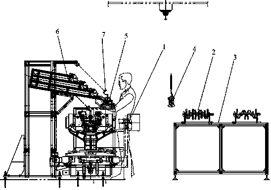
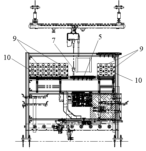
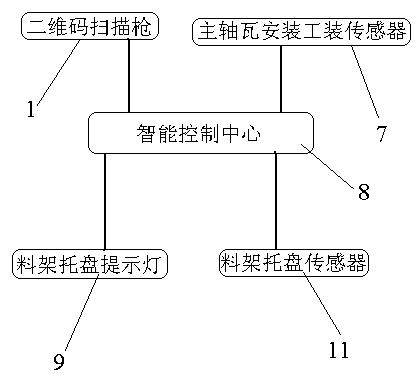
[0018] Example: see figure 1 , figure 2 , image 3 .

[0019] An engine bearing bush assembly process, the process steps are as follows:

[0020] a. Use the QR code scanning gun 1 to scan the QR code pasted on the engine block in advance, and hang the crankshaft 2 from the crankshaft rack to the visual inspection workbench 3;

[0021] b. Check the appearance of the crankshaft 2. After the appearance is qualified, use the QR code scanner 1 to scan the QR code pre-attached to the rear end of the crankshaft 2;

[0022] c. The intelligent control center calculates and compares the cylinder block information sent by the connected two-dimensional code scanning gun 1 with the crankshaft information, obtains the result of tile selection, and starts to light on the intelligent material rack 6 to prompt;

[0023] d. Take the main bearing bush according to the green light of the intelligent material rack 6, and install the main bearing bush in the cylinder block and the main bearing ca


PUM


Abstract

The invention relates to the field of engine assembly, in particular to an engine bearing bush assembling technology. The technology comprises the following steps that two-dimensional codes on an engine cylinder body and the rear end of a crankshaft are scanned through a two-dimensional code scanning gun; an intelligent control center conducts calculation and comparison according to cylinder body information and crankshaft information which are sent by the two-dimensional code scanning gun connected with the intelligent control center, a bush selection result is obtained, and a light shining prompt on an intelligent material rack starts to be conducted; main bearing bushes are taken according to an intelligent material rack green light shining prompt, and the main bearing bushes are installed in the cylinder body and a main bearing cover through a main bearing bush installation tool; main bearing bush installation information is fed back to the intelligent control center through a main bearing bush installation tool sensor, and a green light continuously shines on the intelligent material rack to prompt a next group of main bearing bushes needing to be installed; all the steps are repeated till all main bearing bushes are completely installed. According to the engine bearing bush assembling technology, assembly of selected assembly parts of an engine is completed accurately and rapidly, misoperation is prevented, and the production efficiency is improved.

Description


Claims


Application Information

Patent Timeline
Owner JIANGLING MOTORS
Why Eureka
Try Eureka