Plate clamping fixture

A fixture and plate technology, applied in conveyors, conveyor objects, transportation and packaging, etc., to achieve the effects of simple operation, improved stability, and improved loading efficiency

Inactive Publication Date: 2016-04-20
罗志琼
View PDF5 Cites 1 Cited by
  • Summary
  • Abstract
  • Description
  • Claims
  • Application Information

AI Technical Summary

Problems solved by technology

[0003] In view of this, the technical problem to be solved by the present invention is a plate

Method used


Image

  • Plate clamping fixture

Examples


Embodiment Construction

[0012] In order to allow those skilled in the art to better understand the technical solutions of the present invention, the present invention will be further described below in conjunction with the accompanying drawings.

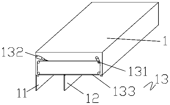
[0013] Such as figure 1 As shown, a plate clamping fixture includes a support frame 1 arranged on a gantry frame. The supporting frame can move back and forth, left and right on the gantry frame. The lower end of the support frame 1 is provided with a front clamping piece 11 and a rear clamping piece 12, and the plate is clamped by the joint action of the front clamping piece 11 and the rear clamping piece 12. The front clip 11 is fixed on one side of the support frame 1, and the rear clip 12 is movably arranged at the lower end of the support frame, and moves back and forth at the lower end of the support frame. In order to be able to drive the rear clip to move back and forth at the lower end of the support frame 1 , the rear clip 12 is connected to a driv


PUM


Abstract

The invention discloses a plate clamping fixture which comprises a supporting frame arranged on a portal frame, wherein a front clamping piece and a rear clamping piece fit with the front clamping piece are arranged at the lower end of the supporting frame; the front clamping piece is fixed at one side of the supporting frame; the rear clamping piece is movably arranged at the lower end of the supporting frame; the rear clamping piece is connected with a driving component, and is driven to move forward and reversely at the lower end of the supporting piece by the driving component; the driving component comprises a host drive, an auxiliary drive and a circularly rotating driving belt; and the driving belt is jointly driven by the host drive and the auxiliary drive. The plate clamping fixture has the advantages of simplicity and convenience in operation, high practicability, and flexibility in use; and a chain can be tensioned to move forwardly, to be kept tightened, and to be locked by the auxiliary drive, so that an augmenting force is applied to the rear clamping piece to clamp a plate, and the clamping stability is improved.

Description


Claims


Application Information

Patent Timeline
Owner 罗志琼
Why Eureka
Try Eureka