Moving column type gantry milling machine driven by single lead screw and assembling technique thereof

A single-screw, gantry milling technology, applied in milling machines, feeding devices, milling machine equipment and other directions, can solve the problems of complex manufacturing process of high-precision equipment, difficult synchronization of double-screw, poor equipment accuracy, etc., to achieve simple and easy installation, Simplified assembly process, cost-saving effect

Inactive Publication Date: 2015-06-10
佛山市南海区精鹰机械有限公司
View PDF5 Cites 0 Cited by
  • Summary
  • Abstract
  • Description
  • Claims
  • Application Information

AI Technical Summary

Benefits of technology

This technology improves how well it works by making sure there're no bending or shaking movements on its movement mechanism when operating at high speeds. It also enhances the accuracy of machinery while reducing their weight without requiring expensive components like motors or hydraulic systems.

Problems solved by technology

This patented describes different designs used for machining columns that move along rails or guides within an industrial facility's main frame. However, these arrangements suffer from various defects like lacked accuracy due to imperfections during production processes caused by factors like vibrations, temperature changes, etc., which makes it challenges to achieve precise movement over long distances without causing damage. Additionally, current methods require multiple motors at once, making their overall efficiency less efficient than desired.

Method used


Image

  • Moving column type gantry milling machine driven by single lead screw and assembling technique thereof
  • Moving column type gantry milling machine driven by single lead screw and assembling technique thereof
  • Moving column type gantry milling machine driven by single lead screw and assembling technique thereof

Examples


Embodiment Construction

[0019] In order to make the technical means, creative features, goals and effects achieved by the present invention easy to understand, the present invention will be further described below in conjunction with specific embodiments.

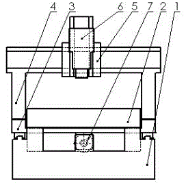
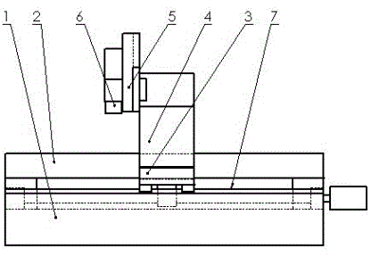
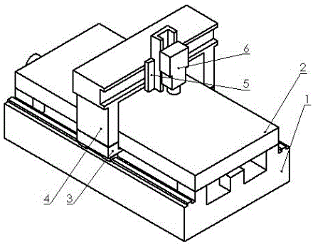
[0020] Such as figure 1 , figure 2 and image 3 As shown, a moving column type gantry milling driven by a single lead screw, including a bed 1, a workbench 2, a sliding table 3, a gantry frame 4, a sliding table 2 5, a spindle assembly 6 and a lead screw 7, the bed Guide rails are provided on both sides of the body 1, the workbench 2 is set above the bed 1 and is rigidly connected with the bed 1, a rectangular gap is provided between the workbench 2 and the bed 1, and the slide table-3 passes through Rectangular gap, and the sliding platform 3 slides along the guide rails on both sides of the bed 1, the gantry 4 is rigidly connected with the sliding platform 3, and is connected into a "mouth"-shaped structure, and the gantry 4 is provided on one s


PUM


Abstract

The invention discloses a moving column type gantry milling machine driven by a single lead screw and an assembling technique of the moving column type gantry milling machine. The moving column type gantry milling machine driven by the single lead screw comprises a bed body, a workbench, a first slide table, a portal frame, a second slide table, a main shaft component and a lead screw, wherein a rectangular gap is arranged between the workbench and the bed body, the first side table passes through the rectangular gap, and the first slide table is glided along lead rails at both sides of the bed body; the portal frame is rigidly connected with the first slide table to form a hollow square shaped structure; a second slide table is arranged between the main shaft component and the portal frame, and the second slide table is crossly glided along a cross arm of the portal frame; the main shaft component is glided in longitudinal direction along the slide rail of the second slide table, and middle part of the bed body is provided with a sole lead screw; the middle position of a bottom part of the slide table is fixed with a lead screw nut. The structure has very good rigidity of the mobile portal frame at the greatest extent, and largely improves the stress deformation of the device at work, promotes equipment precision, simplifies assembling technique; moreover, requirement on the control stem is low, and cost is saved.

Description


Claims


Application Information

Patent Timeline
Owner 佛山市南海区精鹰机械有限公司
Why Eureka
Try Eureka