Fully automatic capsule hole puncher

A punching machine, fully automatic technology, applied in the direction of capsule delivery, drug delivery, pharmaceutical formulations, etc., can solve the problems of harmful health and low production efficiency, and achieve the effects of improving production efficiency, saving personnel costs, and saving production costs

Active Publication Date: 2016-05-25
绍兴易瑞普健康科技有限公司
View PDF7 Cites 0 Cited by
  • Summary
  • Abstract
  • Description
  • Claims
  • Application Information

AI Technical Summary

Problems solved by technology

In the current society, for most smokers, smoking is an indispensable necessity in life, and smoking is harmful to health, so people use capsules to hold drugs and place them in the filter of electronic cigarettes, so as

Method used


Image

  • Fully automatic capsule hole puncher
  • Fully automatic capsule hole puncher
  • Fully automatic capsule hole puncher

Examples


Embodiment

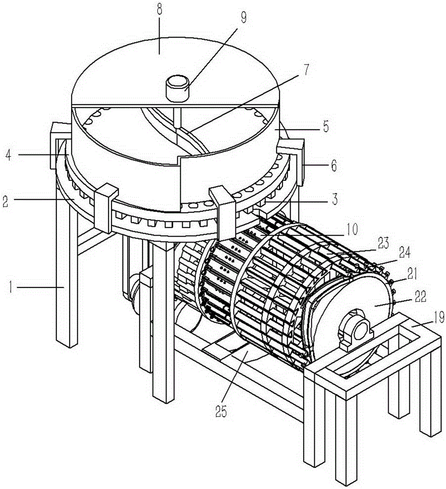
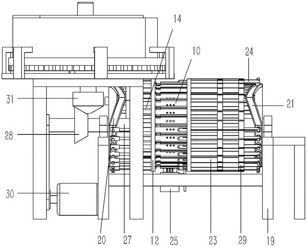
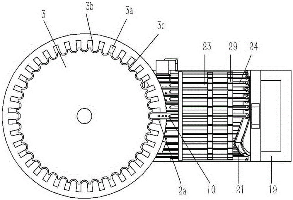
[0028] Example: see Figures 1 to 9 As shown, a fully automatic capsule punching machine includes a main frame 1, a chassis 2 is fixed on the main frame 1, a distribution tray 3 is hinged on the chassis 2, and a tray 4 and a storage box 5 are arranged on the distribution tray 3 , the tray 4 and the material storage box 5 are fixed on the chassis 2 through the connecting bracket 6, the material storage box 5 is provided with a feeding brush 7, the feeding brush 7 is fixed on the rotating shaft of the feeding brush motor 9, and the feeding brush motor 9 is fixed on the cover plate 8, the cover plate 8 is fixed on the top of the material storage box 5, the edge of the material distribution tray 3 is formed with stepped teeth 3a, and a strip-shaped hole 3b is formed between adjacent stepped teeth 3a, and the strip-shaped hole 3b The rear portion is a tapered hole 3c, and the chassis 2 below the bar-shaped hole 3b outside the material storage box 5 is formed with a feed port 2a, and s


PUM


Abstract

The invention discloses a fully automatic capsule hole puncher. The fully automatic capsule hole puncher comprises a main frame, wherein a chassis is fixed on the main frame; a feeding opening is formed in the chassis; a plurality of semicircular groove bases are arranged below the feeding opening; the two ends of the groove bases are respectively fixed on a first supporting hub and a second supporting hub and are uniformly distributed on the first supporting hub in an annular way; a plurality of suction holes are formed in the groove bases; annular air distribution bases are fixed on the lower bottom surfaces of the groove bases; a plurality of independent suction grooves are formed in the air distribution bases; the suction grooves are communicated with the suction holes in the groove bases; a plurality of suction pipes are fixed on the second supporting hub; a plurality of air holes distributed in an annular way around the center of the second supporting hub are formed in the end surface of the left side of the second supporting hub; a fan-shaped suction base is propped against the end surface of the left side of the second supporting hub on the lower side of the feeding opening of the chassis. The fully automatic capsule hole puncher realizes the automatic machining of small holes in capsules, breaks away from manual industry, improves the production efficiency, and meanwhile saves a large amount of staff cost.

Description


Claims


Application Information

Patent Timeline
Owner 绍兴易瑞普健康科技有限公司
Why Eureka
Try Eureka