Stable and controllable time delay switch

A time-delay switch and stable technology, applied in thyristors, circuits, semiconductor devices, etc., can solve problems such as the inability of time-delay switches to be adjusted, and achieve the effects of low manufacturing cost, long service life and convenient use.

Pending Publication Date: 2021-02-09
邵清平
View PDF0 Cites 0 Cited by
  • Summary
  • Abstract
  • Description
  • Claims
  • Application Information

AI Technical Summary

Benefits of technology

This patented technology allows for easy self-resetting or adjustable timing without requiring manual interference between different parts like turning back on/off power supply and dimming controls. Additionally, this design prevents excessive heat generation due to insufficient coolant circulation within the system's components such as pumps and motors. Overall, these technical features improve efficiency, reliability, durability, and usages compared to existing designs.

Problems solved by technology

The technical problem addressed by this patented technology relates to improving the efficiency and convenience associated with switching devices when they're being controlled remotely through remote controls on multiple locations without wasting power resources due to frequent manual operation.

Method used


Image

  • Stable and controllable time delay switch
  • Stable and controllable time delay switch
  • Stable and controllable time delay switch

Examples


Embodiment

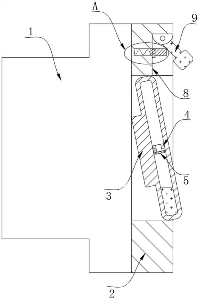
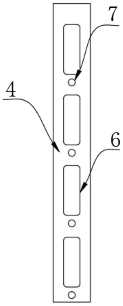
[0019] refer to Figure 1-4 , a stable and controllable time-delay switch, including a wiring body 1 and a panel 2 installed on it, the inner wall of the panel 2 is rotatably connected with a push cover 3, and the inner wall of the press cover 3 is fixed with a partition plate 4, the partition plate The upper end of 4 is provided with a plurality of fast-falling grooves 6 and slow-release holes 7, and the bottom of the partition plate 4 is connected with a plurality of baffle plates 5 corresponding to a plurality of fast-falling grooves 6 one by one through a torsion spring. The aperture of 6 is obviously larger than the slow-release hole 7, and the baffle plate 5 closes the lower part of the quick-falling groove 6, so that the quick-falling groove 6 can only pass through from top to bottom, and cannot flow in reverse. The upper wall of the panel 2 is provided with a conversion groove 8, The inner wall of the transfer tank 8 is rotatably connected with a rotary block 9 .

[0020


PUM


Abstract

The invention discloses a stable controllable time-delay switch, which comprises a wiring body and a panel installed on the wiring body, and is characterized in that the inner wall of the panel is rotatably connected with a pressing cover, the inner wall of the pressing cover is fixedly provided with a partition plate, and the upper end of the partition plate is provided with a plurality of quickfalling grooves and slow release holes in a penetrating manner; the bottom of the partition plate is rotationally connected with a plurality of baffles in one-to-one correspondence with the quick falling grooves through torsional springs, a conversion groove is formed in the upper wall of the panel, and a rotating block is rotationally connected to the inner wall of the conversion groove. The magnetic fluid lamp has the advantages that the quick-falling groove and the slow-release hole which are large in hole diameter difference are formed in the partition plate, the baffle is installed at theposition of the quick-falling groove, the magnetic fluid can only pass through the slow-release hole with the small hole diameter in the upward moving process, and therefore the vertical flowing speed of the magnetic fluid is obviously different, and the lighting process of lamplight is rapidly completed; and a certain time is needed in the closing process, the effect of delayed closing is achieved, electronic equipment is not involved, the manufacturing cost is lower, and the service life is longer.

Description


Claims


Application Information

Patent Timeline
Owner 邵清平
Why Eureka
Try Eureka