Zinc oxide nano material resistance measurement method and device

A zinc oxide nanometer and resistance measurement technology, which is applied in the direction of measuring devices, measuring electrical variables, measuring resistance/reactance/impedance, etc., can solve the problems of increasing experimental costs and achieve the effect of reducing costs

Inactive Publication Date: 2016-06-08
HARBIN UNIV OF SCI & TECH
View PDF5 Cites 1 Cited by
  • Summary
  • Abstract
  • Description
  • Claims
  • Application Information

AI Technical Summary

Benefits of technology

This patented method involves measuring changes caused when certain materials are exposed to high temperatures or pressures during their manufacture process. By utilizing this technique, researchers have been able to accurately predict how well these new material will behave under specific conditions for use at various stages throughout its production cycle.

Problems solved by technology

This patented technical problem addressed by this patents relates to how to measure the properties or characteristics of nano-materials like zincoxide without requiring expensive laboratory facilities for testing purposes.

Method used


Image

  • Zinc oxide nano material resistance measurement method and device

Examples


Embodiment 1

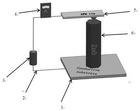
[0012] A method and device for measuring the resistance of zinc oxide nanomaterials, comprising: a conductive substrate 1, the conductive substrate is connected to a wire (1), the wire (1) 2 is connected to a power supply, and the power supply passes through the wire (2) connected to the ammeter 3, the ammeter is connected to the atomic force microscope probe 4 through the wire (3), the atomic force microscope probe is in contact with the zinc oxide nanomaterial 5, and the zinc oxide nanomaterial is in contact with the conductive substrate 6 to form a closed loop.

Embodiment 2

[0014] According to the method and device for measuring resistance of zinc oxide nanomaterials described in Example 1, the probe tip of the atomic force microscope is partially coated with a gold layer.


PUM


Abstract

The invention provides a zinc oxide nano material resistance measurement method and device. A zinc oxide nano material is widely used in manufacturing of electric equipment such as nano power generators, gas sensors and memory storage devices. In the prior art, when the resistance of the zinc oxide nano material needs to be measured, micro-electrical manufacturing and specially designed equipment are needed, and it is inevitable that experiment cost is increased. The zinc oxide nano material resistance measurement device comprises a conductive substrate connected with a first wire, the first wire is connected with a power source, the power source is connected with an ampere meter through a second wire, the ampere meter is connected with an atomic force microscope probe through a third wire, the atomic force microscope probe makes contact with the zinc oxide nano material which is connected with the conductive substrate, and accordingly a closed loop is formed.

Description


Claims


Application Information

Patent Timeline
Owner HARBIN UNIV OF SCI & TECH
Why Eureka
Try Eureka