Lighting indicator structure for electronic device

A technology for electronic devices and indicators, which is applied to the components of lighting devices, measuring devices, lighting devices, etc., and can solve the problems of increased bulkiness of cover assemblies, damage to the robustness and durability of electronic devices, etc.

Active Publication Date: 2019-02-15
TACTOTEK
View PDF12 Cites 0 Cited by
  • Summary
  • Abstract
  • Description
  • Claims
  • Application Information

AI Technical Summary

Problems solved by technology

[0003] However, the provision of such an integrated backlight can lead to increased bulkiness of the cover assembly, which is often undesirable
Fu

Method used


Image

  • Lighting indicator structure for electronic device
  • Lighting indicator structure for electronic device
  • Lighting indicator structure for electronic device

Examples


Embodiment Construction

[0016] The following description and drawings sufficiently illustrate specific embodiments to enable any person skilled in the art to practice and / or implement the disclosed systems, methods, and / or apparatuses. Other embodiments may incorporate structural, operational, and other changes. Portions and features of some embodiments can be included in or substituted for those of other embodiments.

[0017] One aspect of the invention includes an assembly for forming part of an electronic device, the assembly comprising:

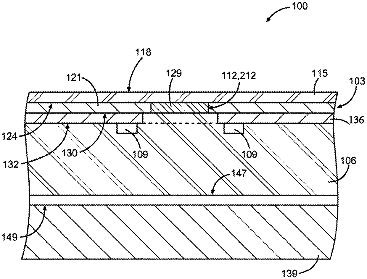
[0018] a substantially opaque cover member configured to be incorporated into the electronic device to shield one or more other components of the electronic device from view, the cover member having an outer surface and an opposing inner surface, wherein the cover member has a thickness dimension extending transversely between the outer surface and the inner surface;

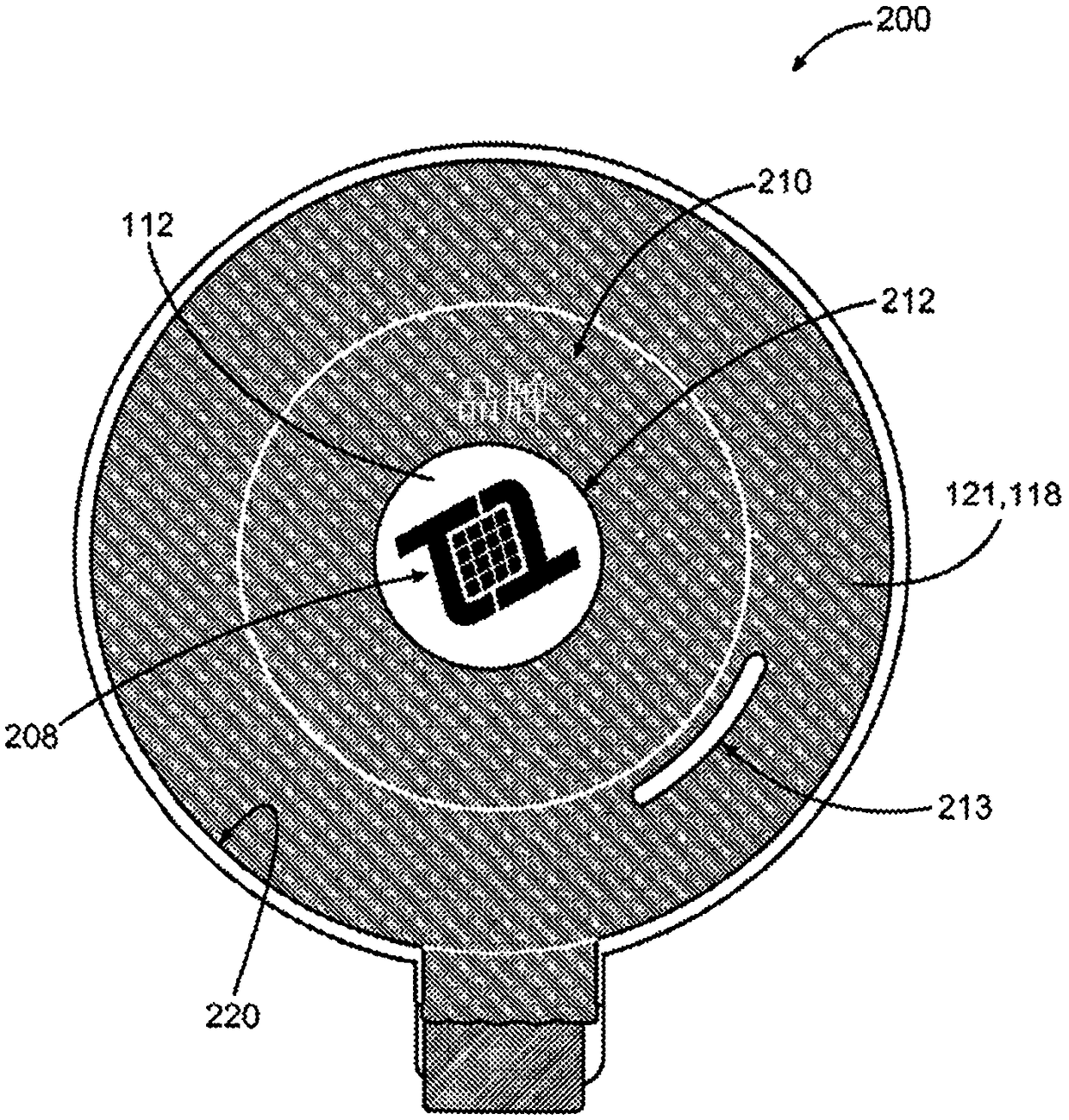
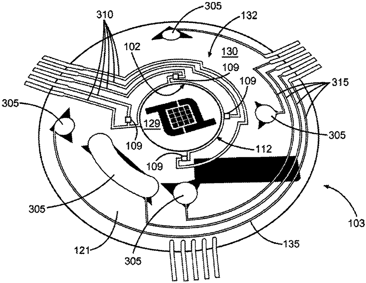
[0019] one or more indicator structures in the cover member, each indicator structure havin


PUM


Abstract

A composite laminate assembly for an electronic device is disclosed that provides integrated backlighting for one or more indicator shapes defined by the assembly. The assembly includes a substantially opaque cover member to shield at least a portion of the electronic device. A translucent indicator structure in the cover member defines a corresponding indicator shape to allow backlighting to pass through the cover member. An optical matrix layer of optically conductive material is attached to the inner surface of the cover member, wherein a plurality of illuminators are embedded in the optical matrix layer and laterally offset from associated indicator structures. The plurality of lighting devices may be connected to electronic circuitry carried on the inner surface of the cover member.

Description


Claims


Application Information

Patent Timeline
Owner TACTOTEK
Why Eureka
Try Eureka