Fastening type vertical sander

A sanding machine, fastening type technology, applied in the direction of grinding machine parts, grinding/polishing equipment, machine tools suitable for grinding workpiece planes, etc., can solve the problems of inefficiency, high batch processing price, roughness, etc. , to achieve the effect of low cost, stable sanding process and improved efficiency

Inactive Publication Date: 2016-09-14
SUZHOU BOLAIXI ELECTRICAL APPLIANCE CO LTD
View PDF8 Cites 0 Cited by
  • Summary
  • Abstract
  • Description
  • Claims
  • Application Information

AI Technical Summary

Problems solved by technology

The existing sanding process of wood originals either uses a hand-held sanding machine to sand one by one, or uses a large sanding machine

Method used


Image

  • Fastening type vertical sander
  • Fastening type vertical sander
  • Fastening type vertical sander

Examples


Embodiment Construction

[0014] Specific embodiments of the present invention will be further described in detail below.

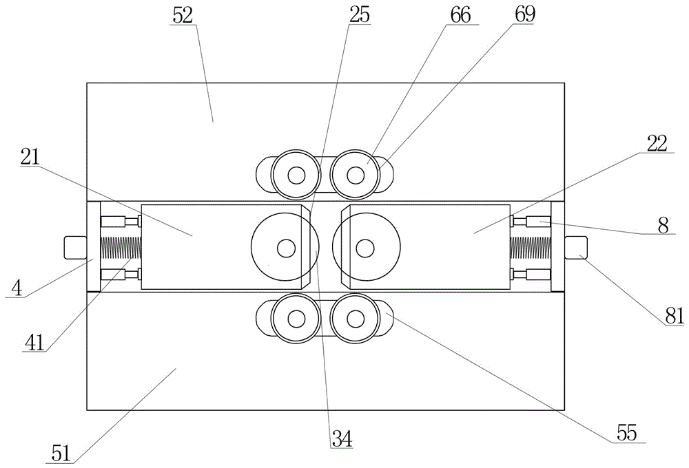
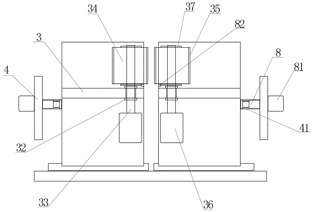
[0015] Such as Figure 1 to Figure 4 As shown, a fastening type vertical sander of the present invention includes a base 1, and the base 1 is provided with a grinding part 2 and a fixing part. It is characterized in that: the grinding part 2 is arranged in the middle of the base 1, and the fixing part is The first fixed part 51 and the second fixed part 52, the first fixed part 51 and the second fixed part 52 are arranged on both sides of the grinding part 2 respectively, and the first fixed part 51 and the second fixed part 52 all include the connecting base 1 The frame 53 and the transverse plate 54 horizontally arranged on the frame 53, the grinding part 2 includes two symmetrically arranged first grinding assemblies 21 and the second grinding assemblies 22, the first grinding assemblies 21 and the second grinding assemblies 22 are Including the first slide rail 23 and the grindi


PUM


Abstract

The invention discloses a fastening type vertical sander. By means of corresponding arrangement and relative rotation of two grinding cylinders of a grinding part, wood materials are placed between the two grinding cylinders; and by means of relative rotation of the grinding cylinders, the aim of grinding the wood materials is achieved. By means of procedures of an assembly line, sanding processing can be conducted on the wood materials in batches, and the processing efficiency is improved. The two sides of each first high-pressure spring are each provided with a telescopic rod. The telescopic rods are connected with grinding boxes. Hydraulic cylinders have an effect on pushing and drawing the telescopic rods. Inductors arranged on first rotation rollers are connected to the hydraulic cylinders. When the inductors induct that the wood materials make contact with the grinding cylinders, the hydraulic cylinders drive the telescopic rods to draw back in good time, the wood materials can enter the portion between the two grinding cylinders, then, the hydraulic cylinders drive the telescopic rods again to push the grinding boxes, the two grinding cylinders conduct extruding and sanding on the wood materials together, and the whole sanding procedure can be more stable.

Description


Claims


Application Information

Patent Timeline
Owner SUZHOU BOLAIXI ELECTRICAL APPLIANCE CO LTD
Why Eureka
Try Eureka