A heart defect occluder
A occluder and heart technology, applied in medical science, surgery, etc., can solve the problems of unreasonable structural setting of heart defect occluder, failure to achieve the best anastomosis effect of heart defect, and achieve the effect of reducing volume
- Summary
- Abstract
- Description
- Claims
- Application Information
AI Technical Summary
Problems solved by technology
Method used
Image

Examples
Example Embodiment
[0035] Example 1
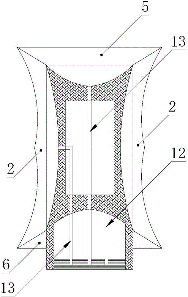
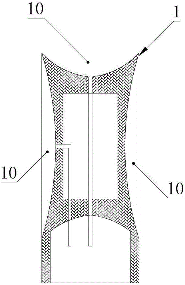
[0036] The upper end of the support frame 1 is provided with an upper positioning body 5 with a preset shape, and the lower end of the support frame 1 is provided with a lower positioning body 6 with a preset shape.
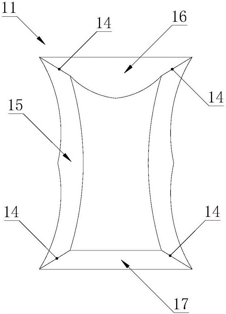
[0037] The combination of the side positioning body 2, the upper positioning body 5 and the lower positioning body 6 forms an integral structure of the balloon 11. The balloon 11 includes an opening. The support frame 1 is arranged at the opening of the balloon 11. The support frame 1 and the ball A sealed cavity 12 is formed between the inner sides of the balloon 11, and the support frame 1 is provided with a pipeline 13 for the cavity 12 to enter or flow out fluid; the envelope structure of the balloon 11 covering the stent frame 1 is adopted to achieve The effect of facilitating the positioning and use of the heart defect occluder.
[0038] When in use: 1. The side positioning body 2, the upper positioning body 5 and the lower positioning body 6 can
Example Embodiment
[0040] Example 2
[0041] The upper end of the support frame 1 is provided with an upper positioning body 5, and the lower end of the support frame 1 is provided with a lower positioning body 6. The upper positioning body 5 and the lower positioning body 6 are both inflatable bodies (similar to balloons) that can be expanded and expanded outwardly by filling fluid. The body is distributed on the circumferential wall of the support frame in an annular shape. When the expansion body is filled with fluid, the expansion body begins to expand outward and expand.
[0042] An upper duct 3 communicating with the upper positioning body 5 and a lower duct 4 communicating with the lower positioning body 6 are provided in the pocket 7 of the support frame 1, so as to inject fluid into the upper positioning body 5 and the lower positioning body 6 respectively. Force it to expand or splay outward.
[0043] One end of the upper duct 3 is connected to the upper positioning body 5, and the other end is
Example Embodiment
[0045] Example 3
[0046] A cardiac defect occluder includes a support frame 1, a side positioning body 2, an upper positioning body 5, a lower catheter 4 and a lower positioning body 6.
[0047] The side part of the support frame 1 is provided with a side positioning body 2, the middle of the support frame 1 is provided with a receiving groove 7, and the bottom end of the receiving groove 7 is open, and the receiving groove 7 of the support frame 1 is connected to the side positioning body 2 The side duct 8 is used to inject fluid into the side positioning body 2 to force it to expand toward or expand outward.
[0048] In a preferred embodiment, one end of the side pipe 8 is connected to the side positioning body 2, and the other end is filled with a rubber plug 9.
[0049] The upper end of the support frame 1 is provided with an upper positioning body 5, which is connected to the side positioning body 2. The upper positioning body 5 is an expansion body (similar to a balloon) that can
PUM
 Abstract
Description
Claims
Application Information
 - R&D Engineer
- R&D Manager
- IP Professional
- Industry Leading Data Capabilities
- Powerful AI technology
- Patent DNA Extraction
Browse by: Latest US Patents, China's latest patents, Technical Efficacy Thesaurus, Application Domain, Technology Topic.
© 2024 PatSnap. All rights reserved.Legal|Privacy policy|Modern Slavery Act Transparency Statement|Sitemap