Intelligent paying-off device for power construction and working method of intelligent paying-off device

A technology of pay-off device and electric construction, applied in the directions of transportation and packaging, transportation of filamentous materials, and thin material handling, etc., can solve the problems of consuming the physical strength of construction personnel, increasing construction costs, and low technical content, and reducing the workload. , the effect of reducing wear and improving safety

Active Publication Date: 2016-10-26
NINGXIA HUI AUTONOMOUS REGION ELECTRIC POWER DESIGN INST
View PDF6 Cites 1 Cited by
  • Summary
  • Abstract
  • Description
  • Claims
  • Application Information

AI Technical Summary

Benefits of technology

This patented technology describes an improved system called Intelligent Pay Off (IOP) or Automatic Line Plan System (ALPS). These systems replace traditional methods like human guards and electronic devices such as cameras but they have several advantages over them. One advantage being able to automatically adjust the routing based upon predetermined rules while maintaining security against collisions. Another benefit includes reducing labor costs associated with manually installing lines within buildings due to reduced effort required. Additionally, these technologies allow for automatic operations along any direction needed, increasing efficiency and productivity. Overall, this innovative solution simplifies the overall structure and maintenance management of electrical equipment installations.

Problems solved by technology

This patented technology allows for electricity transmission and reconfiguration without requiring manual labor from workers who are needed to move wire bundles around with their hands during building construction.

Method used


Image

  • Intelligent paying-off device for power construction and working method of intelligent paying-off device

Examples


Embodiment

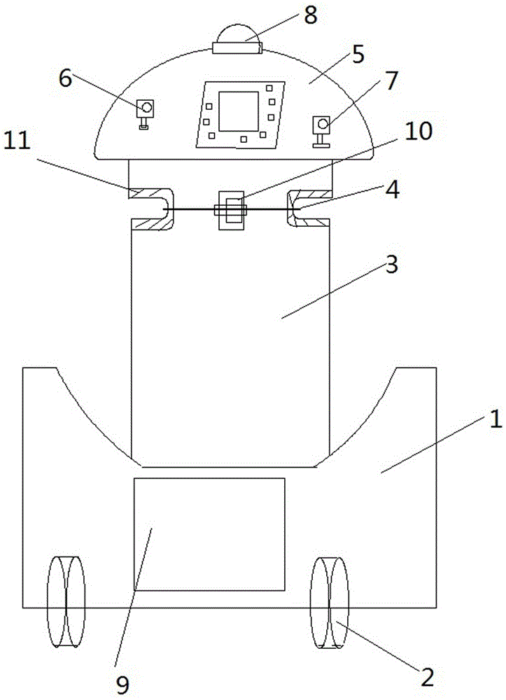
[0039] Such as figure 1The shown one is an intelligent pay-off device used in the electric power construction process, including: base 1, caster 2, wire column 3, wire and cable 4, limit device 5, position detection device 6, obstacle detection device 7, An alarm device 8 and a control device 9. The control device 9 is provided with an input mechanism, a drive mechanism, a power supply mechanism and a control mechanism, wherein the control mechanism is provided with a position calibration control module, an obstacle detection control module, Alarm control module, route planning module and controller module;

[0040] The relationship between the above components is as follows:

[0041] The casters 2 are arranged below the base 1, the uprights 3 are arranged on the base 1 in a forward-inclined shape, the wire-releasing ends of the wires and cables 4 are arranged on the wire posts 3, and the limiting device 5 is arranged above the line column 3, the position detection device 6, th

Embodiment 2

[0047] The pay-off device described in this embodiment has the same structure as that in Embodiment 1.

[0048] Such as figure 1 The shown one is an intelligent pay-off device used in the electric power construction process, including: base 1, caster 2, wire column 3, wire and cable 4, limit device 5, position detection device 6, obstacle detection device 7, An alarm device 8 and a control device 9. The control device 9 is provided with an input mechanism, a drive mechanism, a power supply mechanism and a control mechanism, wherein the control mechanism is provided with a position calibration control module, an obstacle detection control module, Alarm control module, route planning module and controller module;

[0049] The relationship between the above components is as follows:

[0050] The casters 2 are arranged below the base 1, the uprights 3 are arranged on the base 1 in a forward-inclined shape, the wire-releasing ends of the wires and cables 4 are arranged on the wire p


PUM


Abstract

The invention discloses an intelligent paying-off device for power construction. The intelligent paying-off device comprises a base, trundles, a wire post, a wire/cable, a limiting device, a position detection device, an obstacle detection device, an alarm device and a control device. The position detection device, the obstacle detection device and the alarm device are arranged in the limiting device, and the control device is arranged on the base. The control device is internally provided with an input mechanism, a drive mechanism, a power supply mechanism and a control mechanism. The position detection device, the obstacle detection device, the alarm device, the input mechanism, the drive mechanism and the power supply mechanism are connected with the control mechanism. The paying-off device is provided with the position detection device so that the position where the paying-off device arrives can be detected, data detected through the position detection device is compared with an input appointed position, and then the running path of the paying-off device is constantly planned through a path planning module; and meanwhile, the paying-off device is internally provided with the obstacle detection device, and the running safety of the paying-off device is greatly improved.

Description


Claims


Application Information

Patent Timeline
Owner NINGXIA HUI AUTONOMOUS REGION ELECTRIC POWER DESIGN INST
Why Eureka
Try Eureka