A horizontal rough cutting machine

A machine and rough cutting technology, which is applied in the direction of cutters, harvesters, agricultural machinery and implements, etc., can solve the problems of unfavorable storage, fixed frame structure, maintenance hazards, etc., to facilitate maintenance and replacement, reduce storage area, and improve The effect of cutting strength

Inactive Publication Date: 2018-03-02
ZHEJIANG LEKELAI MACHINERY
View PDF4 Cites 0 Cited by
  • Summary
  • Abstract
  • Description
  • Claims
  • Application Information

AI Technical Summary

Problems solved by technology

However, the existing rough cutting machine has the disadvantages of the following aspects: 1. The existing rough cutting machine is relatively large in size and is suitable for weeding in farmland; but its frame structure is fixed and occupies a large space, which is not conducive to storage
Secondly, the cutting parts of this type of rough cutting machine are at the bottom of the frame. If the cutting parts are loose, the rough cutting machine needs to be lifted by the hanger for maint

Method used


Image

  • A horizontal rough cutting machine
  • A horizontal rough cutting machine
  • A horizontal rough cutting machine

Examples


Example Embodiment

[0016] The preferred embodiments of the present invention will be described in further detail below with reference to the accompanying drawings.

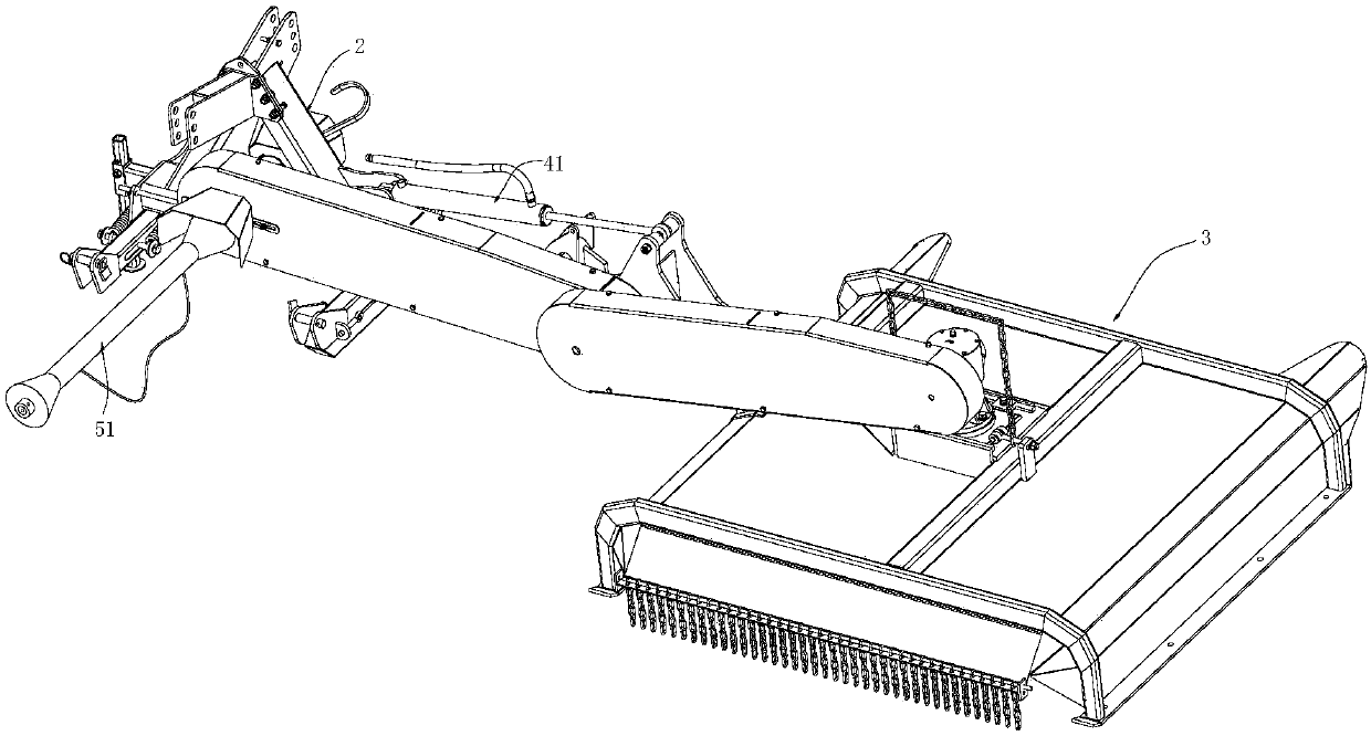
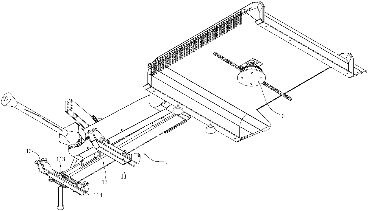
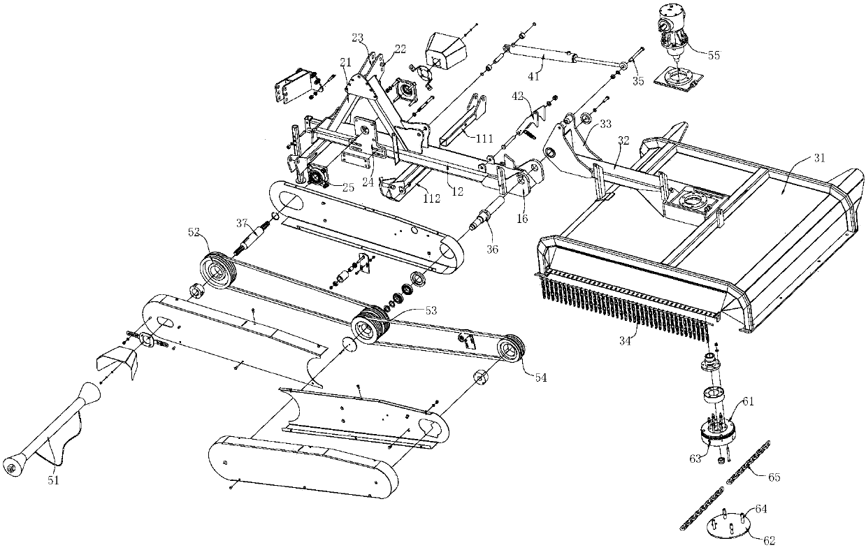
[0017] like Figures 1~3 The shown horizontal rough cutting machine includes a frame, and a transmission assembly and a cutting assembly 6 arranged on the frame. The frame includes a pull frame assembly 1 , a top frame 2 arranged on the pull frame assembly 1 , and a casing assembly 3 connected to the end of the pull frame assembly 1 .

[0018] The pull frame assembly 1 includes two sets of pull frame bottom pipes 11 arranged in parallel with each other, and a pull frame 12 fixed on the two sets of pull frame bottom pipes 11. The setting direction of the pull frame is perpendicular to the setting direction of the pull frame bottom pipes 11. Both ends of the bottom pipe 11 are provided with lower hanging grooves 13 . The bottom tube 11 of the pull frame includes a pull frame inner tube 111 and a pull frame sleeve 112 sleeved with the p


PUM


Abstract

The invention relates to the field of agricultural machinery and especially relates to a horizontally-moving coarse cutting machine. The horizontally-moving coarse cutting machine comprises a rack as well as a transmission assembly and a cutting assembly disposed on the rack, wherein the rack comprises a pull frame assembly, a top frame disposed on the pull frame assembly and a machine case assembly connected to the end part of the pull frame assembly. The horizontally-moving coarse cutting machine has the advantages that the structure is novel; on one side, floor space of the machine can be reduced through rack folding, so that the machine can be stored and maintained easily; and on the other side, cutting components are improved, so that the machine is applicable to high-strength cutting.

Description


Claims


Application Information

Patent Timeline
Owner ZHEJIANG LEKELAI MACHINERY
Why Eureka
Try Eureka