Steam compressor

A compressor and steam technology, applied in the direction of machines/engines, components of pumping devices for elastic fluids, non-variable pumps, etc., can solve the problems of polluted volute, efficiency drop, equipment failure, etc., and achieve sealing Good performance, improve production efficiency and avoid emulsification

Active Publication Date: 2016-12-07
浙江中机环保科技股份有限公司
View PDF7 Cites 0 Cited by
  • Summary
  • Abstract
  • Description
  • Claims
  • Application Information

AI Technical Summary

Benefits of technology

This innovation helps improve how compressed gases are made from liquid without losing their quality due to evaporation during storage over time. It achieves this through an enclosed space where there're no direct contact between the two components that can cause harmful substances like oxygen (O2) or liquids.

Problems solved by technology

This technical problem addressed in this patented text relates to improving the performance of an air compression device (AC) that uses multiple effect evaprosion systems for condensate recovery without adding too much space on top of other parts like pumps.

Method used


Image

  • Steam compressor
  • Steam compressor
  • Steam compressor

Examples


Embodiment Construction

[0015] Embodiments of the present invention will be further described below with reference to the accompanying drawings:

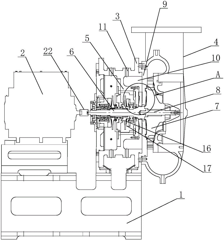
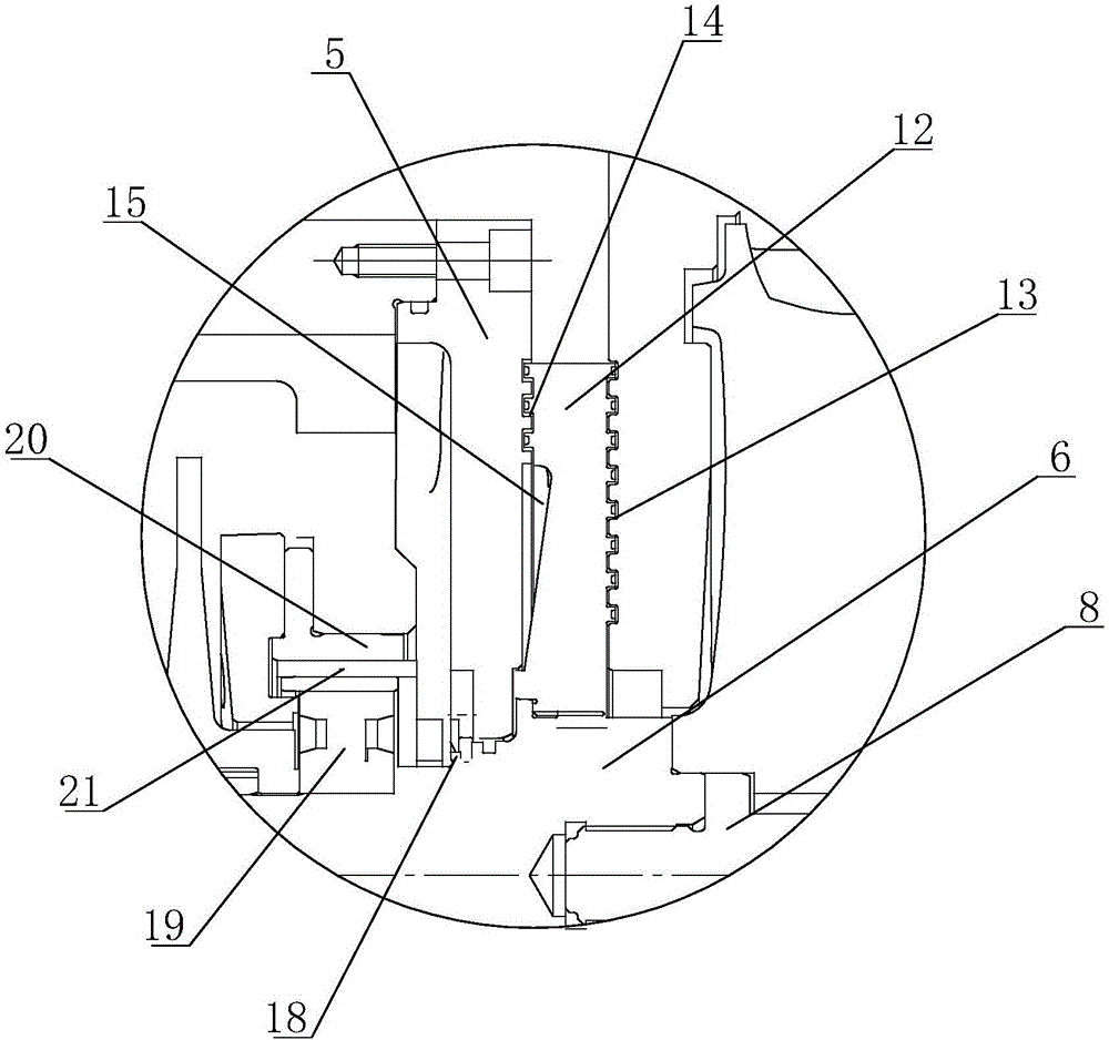
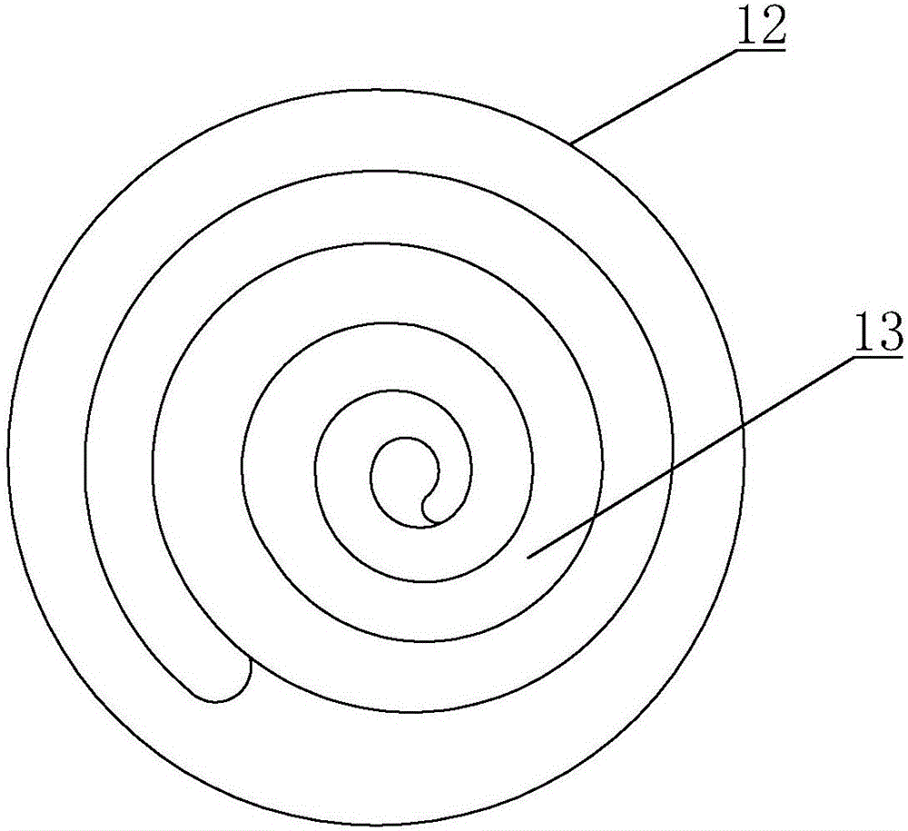
[0016] As shown in the figure, a vapor compressor includes a base 1, a motor 2, a casing 3, a volute 4, a transition box 5 and a main shaft 6, the transition box 5 is located in the casing 3, and the volute 4 is provided with There are blades 7 and blade shafts 8, a partition 9 is provided between the casing 3 and the volute, the main shaft 6 runs through the transition box 5 and is connected to the blade shaft 8 through the partition 9, and the partition 8 and A chamber 10 is provided between the transition box 5, a vent hole 11 communicating with the chamber 10 is provided on the housing 3, a sealing ring 12 is provided between the partition plate 9 and the transition box 5, and the sealing ring 12 is sleeved outside the main shaft 6, one end face of the sealing ring 12 is matched with the surface of the partition 9, the other end face is matched with the s


PUM


Abstract

The invention relates to a steam compressor, and mainly solves the problem of equipment faults caused by emulsification of lubricating oil in a transition box or pollution of volute steam due to weaker tightness of a traditional steam compressor. The steam compressor comprises a base, a motor, a shell, a volute, a transition box and a main shaft; a separation plate is arranged between the shell and the volute; the main shaft penetrates through the transition box and the separation plate to connect with a blade shaft; an accommodating cavity is formed between the separation plate and the transition box; a sealing ring is arranged between the separation plate and the transition box, and coats the main shaft; two end surfaces of the sealing ring are respectively matched with the separation plate and the transition box; a first spiral groove and a second spiral groove are formed in the sealing ring; and a sealing cavity is formed between the sealing ring and the transition box. The steam compressor adopts a sealing structure, solves the leakage problem of the volute and the transmission box of the compressor, effectively improves the production efficiency, and prevents emulsification of the lubricating oil in the transition box, pollution of steam in the volute by the oil and leakage of precious gas or poisonous and flammable gas.

Description


Claims


Application Information

Patent Timeline
Owner 浙江中机环保科技股份有限公司
Why Eureka
Try Eureka