Steam generation tank for power station

A power station and generation tank technology, applied in the field of solar power generation, can solve the problems of heat energy transmission loss, reduce heat engine power generation efficiency, etc., and achieve the effects of improving efficiency, improving efflux efficiency, and speeding up discharge

Inactive Publication Date: 2017-03-22
付建军
View PDF0 Cites 0 Cited by
  • Summary
  • Abstract
  • Description
  • Claims
  • Application Information

AI Technical Summary

Benefits of technology

This patented technology improves upon existing systems by providing a more efficient way of injecting steam onto a specific area during operation or generating energy through combustion processes. It also includes various technical features such as adjustable baffles at different positions inside the tank's roof to control how much liquid enters therein when being used without condensation issues (condensed liquids). Additionally, multiple solar internal heat pipelines may be placed next to one another within certain areas to enhance their effectiveness while minimizing any potential problems caused due to excessive evaporation over time. Overall, this new system allows for better utilization of sunlight resources and improved performance of thermal engines.

Problems solved by technology

The technical problem addressed for this patented technology relating to improving the performance of solar-thermal systems used for generating electricity without causing excessive loss during their operation due to condensation of small liquid particles on pipes carrying fluids containing high temperatures.

Method used


Image

  • Steam generation tank for power station
  • Steam generation tank for power station

Examples


Embodiment 1

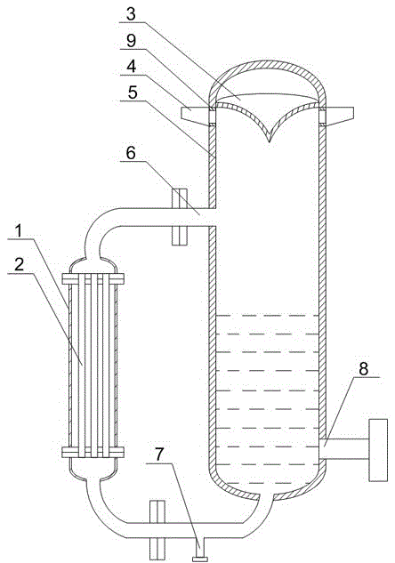
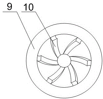
[0022] Such as figure 1 with figure 2 As shown, the present embodiment includes a tank body 5 and a solar external heat pipe 1, the bottom of the tank body 5 communicates with the bottom of the solar external heat pipe 1 through a conduit, and the middle part of the tank body 5 communicates with the top of the solar external heat pipe 1 through a conduit. The side wall of the tank body 5 is provided with a liquid inlet pipe 8, and two mutually symmetrical air outlet pipes 4 are arranged on the top side wall of the tank body 5, and the inner walls of the two air outlet pipes 4 are rotated to be provided with Nozzle 9, and a plurality of spiral protrusions 10 are installed on the inner wall of the nozzle 9, a deflector 3 is fixed on the top of the tank body 5, the middle part of the deflector 3 protrudes downward to form an inverted cone, and the The outer conical surface of the inverted cone is bent inward along its center line, and the axis of the air outlet pipe 4 is facing th


PUM


Abstract

The invention discloses a steam generation tank for a power station. The steam generation tank comprises a tank body and a solar outer heat pipe. A liquid inlet pipe is formed in the side wall of the tank body, two gas outlet pipes which are symmetrical are formed in the side wall of the top end of the tank body, nozzles are rotationally arranged on the inner walls of the two gas outlet pipes, a plurality of spiral protrusions are installed on the inner walls of the nozzles, a diversion plate is fixed to the top end of the tank body, the axis of each gas outlet pipe is right opposite to the bend outer conical surface, and a solar inner heat pipe is fixed into the solar outer heat pipe through a flange plate. According to the steam generation tank, after steam is discharged into the tank body, the diversion plate with the middle portion downwards protruding to form an inverted cone is arranged on the top of the tank body, the inverted conical outer conical surface bends inwards along the center line of the inverted cone, that is, the longitudinal cross section of the inverted cone is in an inverted ridge shape, the diversion plate provides curve path guiding for the movement of steam, discharging of the steam is accelerated, and meanwhile the situation that steam is accumulated on the top of the tank body, consequently, part of steam is fused and then freely descends is avoided.

Description


Claims


Application Information

Patent Timeline
Owner 付建军
Why Eureka
Try Eureka