Partitioned simulation method for nuclear power unit condenser

A simulation method and condenser technology, applied in the field of simulation, can solve problems such as inability to differentiate calculations, inability to consider small differences in internal pressures of equipment, inability to reflect thermal parameters at different positions, etc. Effect

Active Publication Date: 2017-03-22
HARBIN ENG UNIV
View PDF1 Cites 11 Cited by
  • Summary
  • Abstract
  • Description
  • Claims
  • Application Information

AI Technical Summary

Problems solved by technology

The condenser simulation method based on the lumped parameter method cannot take into account the small differences in the internal pressure of the equipment; the existing partition simulation method is partitioned for the axial direction, which can only reflect the flow sequence and cannot reflect the difference in thermal parameters at differ

Method used


Image

  • Partitioned simulation method for nuclear power unit condenser
  • Partitioned simulation method for nuclear power unit condenser
  • Partitioned simulation method for nuclear power unit condenser

Examples


Embodiment Construction

[0041] The present invention will be further described below in conjunction with the accompanying drawings.

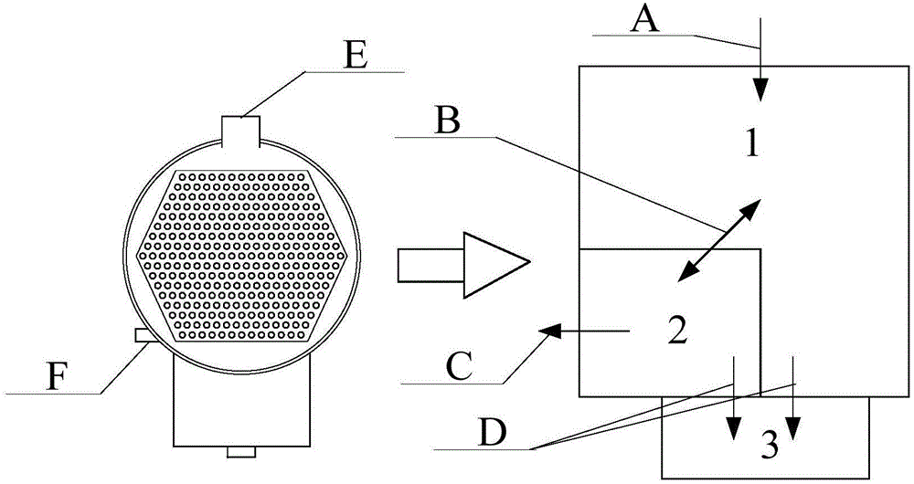
[0042] to combine figure 1 , the implementation steps of the present invention mainly include:

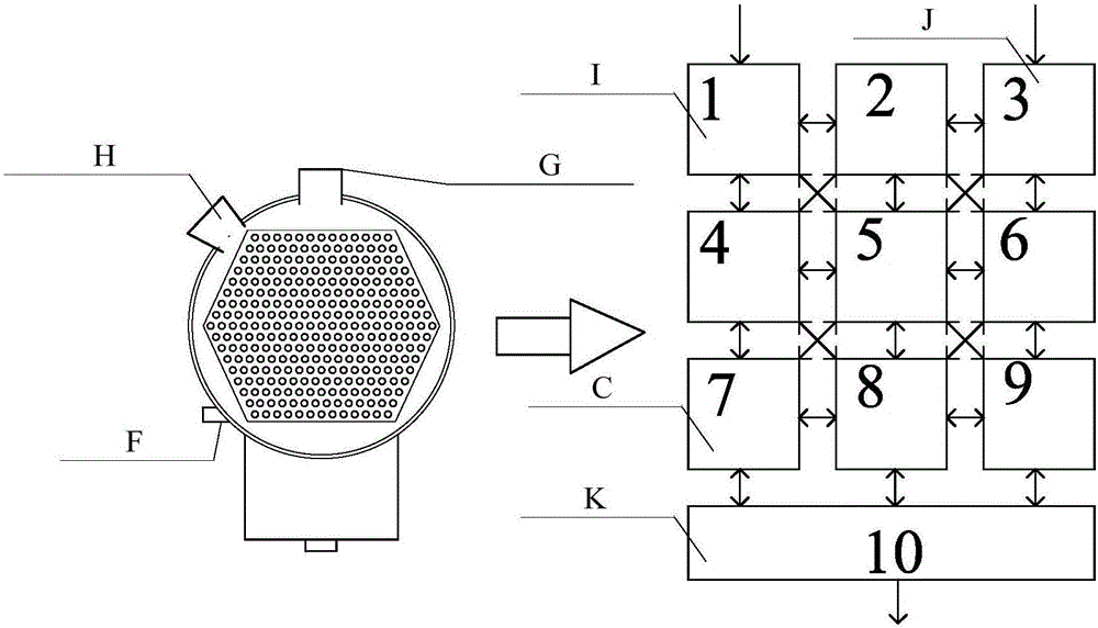
[0043] (1) According to the simulation object, it can be divided into two types: ordinary condenser and shared condenser; according to the division form, it can be divided into two types: uniform partition and non-uniform partition. The specific implementation method is determined as follows:

[0044] a. For the non-uniform zoning scheme of ordinary condensers, the zoning is carried out according to the layout position of the actual condenser sensor. The divided zoning includes zoning (1) steam turbine exhaust port area, zoning (2) air extractor area, and zoning (3) ) hot well area, partition (4) the area where the sensor is located, partition (5) other shell side areas except the above-mentioned areas, partition (6) pipe side circulating water inlet water chamber, partition (


PUM


Abstract

The invention provides a partitioned simulation method for a nuclear power unit condenser. The method comprises the steps of (1), partitioning simulation objects, wherein the simulation objects comprise general condensers and shared condensers, and partitioning comprises uniform partitioning and non-uniform partitioning; (2), inputting structure sizes, physical properties, boundary parameters and calculation initial values of the condensers; (3), carrying out thermal-transfer calculation on one-to-one correspondence partitions at a shell side and a pipe side; (4), carrying out thermal parameter calculation; and (5), outputting a simulation result. Compared with an actual device, the simulation model established by the method has the advantages that the output data under steady state and transient state condition can satisfy a device simulation precision demand, and the operation characteristic research can be carried out through utilization of the simulation method.

Description


Claims


Application Information

Patent Timeline
Owner HARBIN ENG UNIV
Why Eureka
Try Eureka