Drying room used in workshop and plant

A drying room and factory building technology, which is applied in the direction of drying, dryers, and dryers for static materials, etc., can solve the problems of low space utilization rate of workshops and drying rooms, achieve the effect of improving utilization rate and ensuring aesthetics

Inactive Publication Date: 2017-03-29
HENAN PINGGAO GENERAL ELECTRIC CO LTD +2
View PDF5 Cites 1 Cited by
  • Summary
  • Abstract
  • Description
  • Claims
  • Application Information

AI Technical Summary

Problems solved by technology

[0003] The object of the present invention is to provide a kind of drying room used in the factory building, to solve the problem that the space utilization ratio of the factory building and the drying room is all low in the prior art; The purpose of the present invention is also to provide a kind of workshop using the drying room

Method used


Image

  • Drying room used in workshop and plant
  • Drying room used in workshop and plant
  • Drying room used in workshop and plant

Examples


Example Embodiment

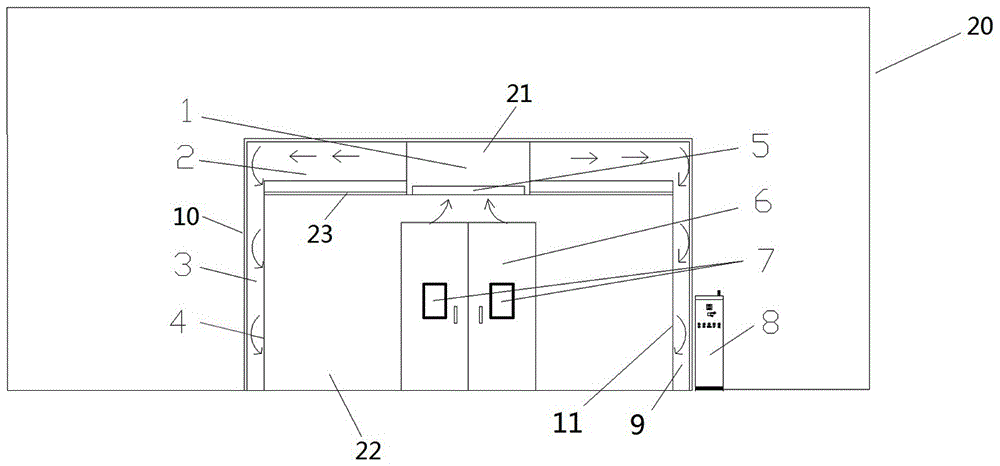
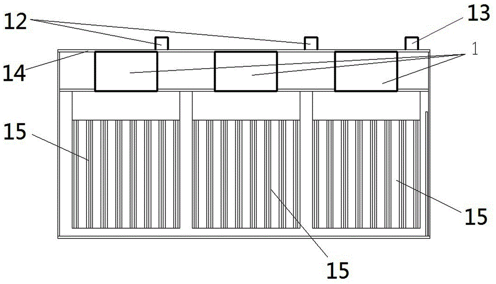
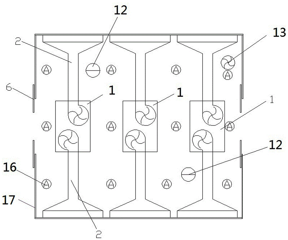
[0027] Workshop implementation example Figure 1~3 Shown: Including a factory building 20 and a drying room 17 set in the factory building. The drying room includes a concrete brick pouring house. The inner cavity of the house is divided into an equipment room 21 and a drying room 22 arranged up and down by a partition 23. The inner walls and partitions of the drying room are provided with thermal insulation layers. The left and right sides of the drying room 22 are provided with a left side wall 4 and a right side wall spaced apart from the left and right side walls of the drying room. 11. Both the front and back sides of the drying room are provided with door 6 for the objects to be dried in and out. There are three hot air devices 1 arranged sequentially in the front and rear directions in the equipment room. Air conditioning units and compressors (not shown in the figure) are also installed in the equipment room 21. Each hot air device 1 includes two independently controlled


PUM


Abstract

The invention relates to a drying room used in a workshop and a plant. The drying room comprises a room body and one or more hot air devices. An inner cavity of the room body is partitioned into a device chamber and a drying chamber through a partition plate, and the device chamber and the drying chamber are arranged vertically. The hot air devices are arranged in the device chamber. Since the inner cavity of the drying room body is partitioned into the device chamber and the drying chamber through the partition plate, and the device chamber and the drying chamber are arranged vertically, so that the originally unused top of the room body is utilized in this way; the hot air devices are arranged in the device room, and the utilization rate of the drying chamber is increased; and in addition, the hot air devices do not occupy the space in the plant excessively any more, and the utilization rate of the plant is increased. The hot air devices are located inside the room body of the drying room, so that the attractiveness of the drying room is guaranteed.

Description


Claims


Application Information

Patent Timeline
Owner HENAN PINGGAO GENERAL ELECTRIC CO LTD
Why Eureka
Try Eureka