Camera shooting system, mobile terminal and image processing method

A camera system and image technology, applied in the field of camera systems, can solve problems such as occupying a large space, and achieve the effect of low power consumption and small volume

Active Publication Date: 2017-04-19
深圳蚂里奥技术有限公司
View PDF6 Cites 29 Cited by
  • Summary
  • Abstract
  • Description
  • Claims
  • Application Information

AI Technical Summary

Benefits of technology

This technology allows for better quality and more accurate imaging than previous methods while also reducing their size or energy usage compared to current technologies like cameras that capture grayscale data from an image sensor.

Problems solved by technology

The technical problem addressed by this patented method is how to efficiently capture high-quality colored image data from various types of sensors while minimizing their size or requiring fewer cameras at once.

Method used


Image

  • Camera shooting system, mobile terminal and image processing method
  • Camera shooting system, mobile terminal and image processing method
  • Camera shooting system, mobile terminal and image processing method

Examples


Embodiment Construction

[0036] The preferred embodiments of the invention will be further described in detail below.

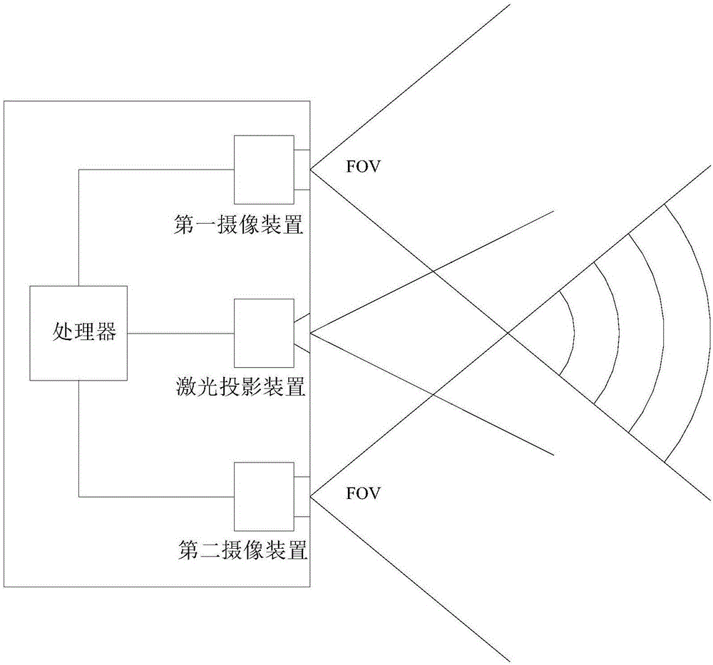
[0037] Such as figure 1 As shown, the camera system of an embodiment includes a first camera device, a second camera device, a laser projection device and a processor, and the processor is electrically connected to the first camera device, the second camera device and the laser projection device respectively.

[0038] The laser projection device is used to project a structured light pattern of invisible laser light to the common field of view of the first camera device and the second camera device; the first camera device is used to collect the images in the shared field of view The first visible light color image and the first invisible light image, the second camera device is used to collect the visible light grayscale image and the second invisible light image in the common field of view; the processor is used to use the first visible light image A visible light color image and a vi


PUM


Abstract

A camera shooting system disclosed by the present invention comprises a first camera shooting device, a second camera shooting device, a laser projection device and a processor. The laser projection device is used to project the structured light patterns of the invisible laser to a common field of view of the first and second camera shooting devices, the first camera shooting device is used to acquire a first visible light color image and a first invisible light image in the common field of view, and the second camera shooting device is used to acquire a visible light gray-scale image and a second invisible light image in the common field of view, and the processor is used to utilize the first visible light color image and the visible light gray-scale image to synthesize a second visible light color image and utilize the first invisible light image and the second invisible light image to calculate a depth image. According to the present invention, the high-quality color image and depth image of a target can be acquired with a smaller size and the lower power consumption.

Description


Claims


Application Information

Patent Timeline
Owner 深圳蚂里奥技术有限公司
Why Eureka
Try Eureka