Anti-thunder illuminating lamp

A lighting fixture, lighting technology, applied in lighting devices, lighting and heating equipment, components of lighting devices, etc., can solve the problems of light waste, light pollution, etc., to improve utilization, reduce light pollution, and reduce invalid light and light pollution. Effect

Inactive Publication Date: 2017-05-10
绍兴华意防雷器材有限公司
View PDF2 Cites 0 Cited by
  • Summary
  • Abstract
  • Description
  • Claims
  • Application Information

AI Technical Summary

Problems solved by technology

The above lamp structure makes the light of the LED light source within the half-power angle range of the upper half not irradiate the road surface or other effective areas tha

Method used


Image

  • Anti-thunder illuminating lamp
  • Anti-thunder illuminating lamp
  • Anti-thunder illuminating lamp

Examples


Embodiment Construction

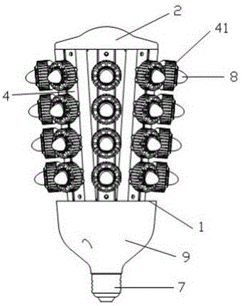
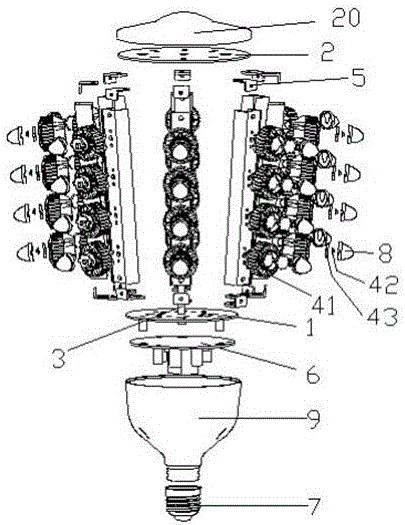
[0021] Such as Figure 1 ~ Figure 4 As shown, the LED landscape lighting lamp 1 provided by the present invention includes a fixed bracket composed of two circular chassis 1, 2, and the two chassis 1, 2 are connected by a thin rod 3 at the center of the circle. Several LED light strips 4 that can be installed and disassembled independently are installed in a circle between the two discs 1 and 2 to form the light source assembly of the LED garden light. Both ends of the LED light bar 4 are respectively fixed on the end faces of the two chassis 1 and 2 through fasteners 5 . A power supply 6 is installed on the other end of the chassis 1, and a lamp cover 9 and a lamp holder 7 are covered outside to connect with an external power supply. The chassis 2 is coated with a high-reflectivity material on one end of the LED light bar 4 , and the bottom cover 20 is installed on the other end.

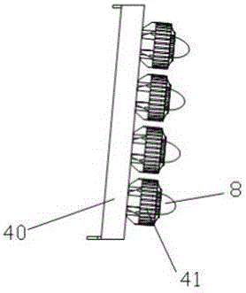
[0022] As shown in FIG. 2, the LED light bar 4 includes a strip-shaped installation base 40, and


PUM


Abstract

An anti-thunder illuminating lamp comprises a light source assembly and a mounting bracket, wherein the light source assembly consists of a plurality of independent light bars which are encircled into a circle, the two ends of the light bars are fixed to the mounting bracket, and a plurality of LED light sources are distributed on the light bars at intervals. The mounting bracket comprises two circular bottom discs, the plurality of light bars are mounted between the two bottom discs at intervals, the radius r of a circle encircled by one ends of the light bars is smaller than the radius R of a circle encircled by the other ends of the light bars, and the whole lamp forms a pagoda shape. The LED scenery illuminating lamp provided by the invention adopts the pagoda-shaped lamp structure, so that the light rays of the LED light sources in power angle ranges are irradiated onto road surfaces or other effective regions as much as possible. The utilizing rate of the light sources is increased, light pollution is greatly reduced, and the heat radiating effect is great.

Description


Claims


Application Information

Patent Timeline
Owner 绍兴华意防雷器材有限公司
Why Eureka
Try Eureka