Suction nozzle structure

A technology of body and support, which is applied in the field of display screen detection equipment, can solve problems such as glass breakage, thin glass deformation and depression, etc., and achieve the effects of avoiding breakage, facilitating installation and adjustment, and ensuring safety

Pending Publication Date: 2017-05-24
SUZHOU JINGLAI OPTO CO LTD
View PDF7 Cites 1 Cited by
  • Summary
  • Abstract
  • Description
  • Claims
  • Application Information

AI Technical Summary

Problems solved by technology

However, as the display panel glass becomes lighter and thinner in recent years, when the suction nozzle absorbs the glass, due to the suction

Method used


Image

  • Suction nozzle structure
  • Suction nozzle structure

Examples


Example Embodiment

[0022] The present invention will be further described in detail below in conjunction with the accompanying drawings and specific embodiments to facilitate a clear understanding of the present invention, but they do not limit the present invention.

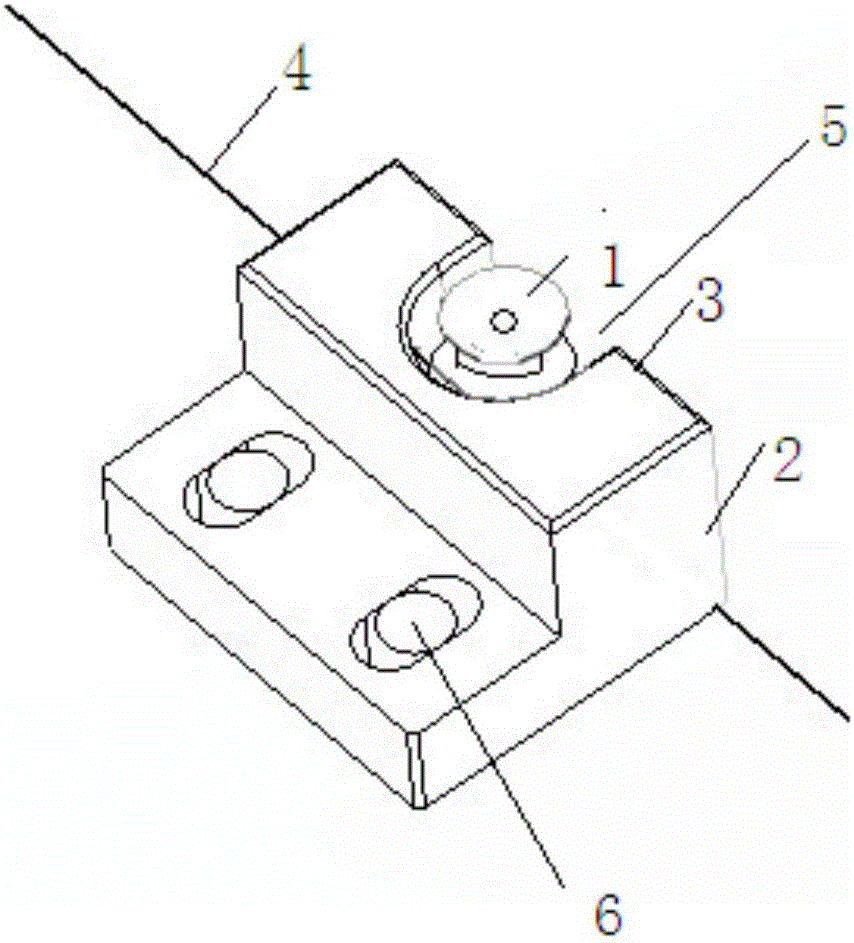
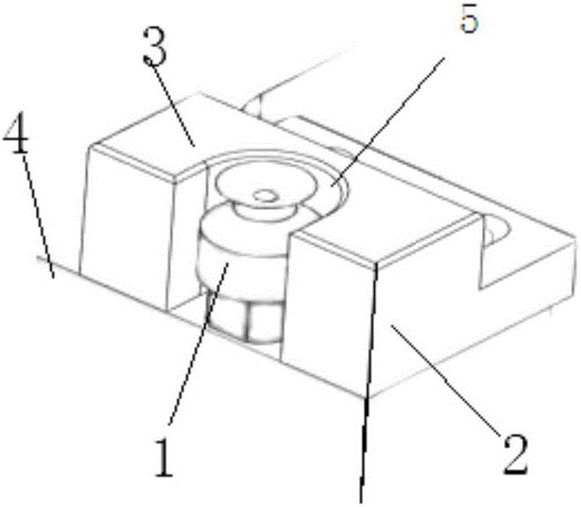
[0023] Such as figure 1 Shown and figure 2 As shown, figure 1 Is a schematic diagram of the nozzle structure of the present invention; figure 2 It is a schematic diagram of the nozzle structure of the present invention from another perspective. This embodiment provides a nozzle structure. The nozzle structure includes a base 4, a nozzle body 1, arranged on the base 4, and a support 2. The support 2 has a support surface 3, and the support surface 3 is located on the suction nozzle. Around the nozzle body 1, the nozzle body 1 is used for sucking the substrate, and is used for supporting the substrate together with the supporting surface 3. In this way, when the suction nozzle body 1 sucks and supports the substrate, the area around t


PUM


Abstract

The invention provides a suction nozzle structure. The suction nozzle structure is characterized by comprising a base, a suction nozzle body and a supporting part; the suction nozzle body is arranged on the base; the supporting part is provided with a supporting face located around the suction nozzle body; the suction nozzle body is used for adsorbing a substrate; and the suction nozzle body and the supporting face are used for supporting the substrate jointly. In order to overcome the defects in the prior art, the suction nozzle structure is provided for supporting in movement of glass.

Description


Claims


Application Information

Patent Timeline
Owner SUZHOU JINGLAI OPTO CO LTD
Why Eureka
Try Eureka