Earthing removing device for mine tunnel

A technology for removing devices and tunnels, applied in the direction of earthmoving machines/shovels, construction, etc., can solve the problems of reducing the service life of tooth bars and tooth tips, large working load, impact load, affecting enterprise benefits, etc., to facilitate excavation. and transport, reduce the resistance of undercutting, and improve the effect of undercutting efficiency

Inactive Publication Date: 2017-05-31
重庆恒晟矿山设备制造厂
View PDF0 Cites 0 Cited by
  • Summary
  • Abstract
  • Description
  • Claims
  • Application Information

AI Technical Summary

Benefits of technology

This new design helps prevent damage caused by excessive pressure on certain parts inside an equipment's bucket due to slippage during digging operations. By having a special structure called this divert slot, which acts like a cushion when compressed against another object while allowing the machine to easily remove materials from different areas without causing any harm. Additionally, there are also specific features within these designs such as reducing the size of the opening through which dirt enters, making them easier to clean compared to existing methods. Overall, these technical improvements help ensure better performance and durability of the machinery used in various industries.

Problems solved by technology

This patented technical problem addressed in this patents relates to how heavy workloads can be experienced by these types of machines during operation causing them to break down or wear out their parts quickly over time.

Method used


Image

  • Earthing removing device for mine tunnel
  • Earthing removing device for mine tunnel

Examples


Embodiment 1

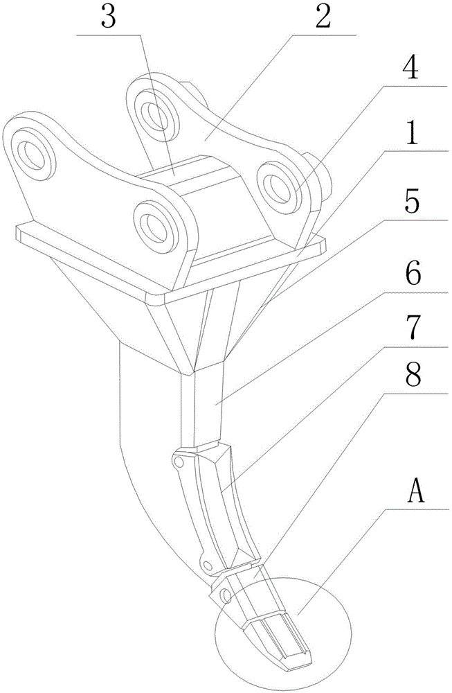
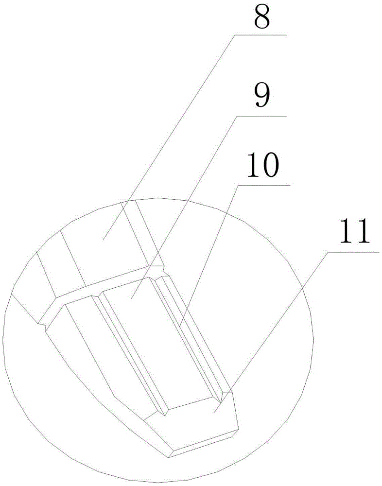
[0019] like figure 1 and figure 2 As shown, this embodiment includes a square connecting plate 1, ear plates 2 with shaft holes 4 are installed on both sides of the upper part of the connecting plate, and a trapezoidal reinforcing plate 3 is welded between the two ear plates 2, An arc-shaped gear bar 6 with bucket teeth 9 is welded at the middle of the bottom of the connecting plate 1, and a reinforcing plate 5 is welded between the square peripheral edge of the connecting plate 1 and the outer wall of the gear bar 6, An alloy sheath 7 is installed on the inner side of the arc-shaped curved surface of the tooth bar 6 through a pin shaft, and a gear sleeve 8 is installed on the upper part of the bucket tooth 9 through a pin shaft. An arc-shaped diversion groove 10, and the diversion groove 10 extends along the direction from the bottom of the bucket tooth 9 to the bottom of the tooth sleeve 8, and the depth of the diversion groove 10 increases along its extending direction. Dur


PUM


Abstract

The invention discloses an earthing removing device for a mine tunnel. The earthing removing device comprises a square connecting plate. Ear plates with shaft holes are mounted on two sides of the upper part of the connecting plate. A trapezoidal reinforcing plate is welded between the two ear plates. An arc-shaped toothed bar with a bucket tooth is welded in the middle of the bottom of the connecting plate. A stiffening plate is welded between the peripheral edge of the square connecting plate and the outer wall of the toothed bar. An alloy sheath is mounted on the inner side of an arc-shaped curved surface of the toothed bar by means of a pin. A toothed sleeve is mounted at the upper part of the bucket tooth by means of a pin. Two arc-shaped guide grooves are formed in the inside wall of the lower part of the bucket tooth, and extend in the direction from the bottom of the bucket tooth to the bottom of the toothed sleeve. The depths of the guide grooves are progressively increased in the extending direction of the guide grooves. Since the depths of the guide grooves are progressively increased in the extending direction of the guide grooves, with the penetration of the bucket tooth, a space for releasing the extrusion force action between the inside wall of the bucket tooth and a material matrix is gradually increased, and the downwards cutting efficiency of the bucket tooth is further improved.

Description


Claims


Application Information

Patent Timeline
Owner 重庆恒晟矿山设备制造厂
Why Eureka
Try Eureka