Ring with three color-light-emitting bulbs

A technology of rings and light bulbs, applied in rings, clothing, applications, etc.

Inactive Publication Date: 2017-06-20
马天野
View PDF0 Cites 0 Cited by
  • Summary
  • Abstract
  • Description
  • Claims
  • Application Information

AI Technical Summary

Benefits of technology

This technology allows for an illumination system with lights attached to rings or other items like tablesets without adding too much weight or making them look unhealthy looking at their surface.

Problems solved by technology

This patented problem with ring lights has been solved by adding lamps or other devices attached to them for added decoration purposes like ornamenting or providing more visual appeal during certain times when there's insufficient sunlight available at nightfall.

Method used


Image

  • Ring with three color-light-emitting bulbs

Examples


Embodiment Construction

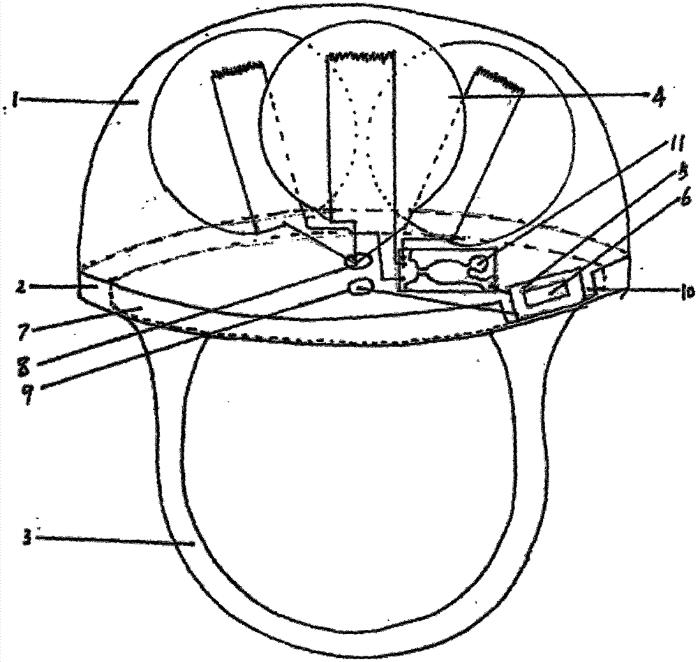
[0012] The patent of the present invention is that a battery is arranged on the ring tray, and a light control sheet is pasted on the battery. One connection point of the three parallel bulbs is connected to the positive pole of the battery, and the other connection point of the three light bulbs is respectively glued to the connection point at one end of the light control sheet. Connect, the two ends of the switch are respectively connected to the light control sheet and the negative pole of the battery to form a complete circuit, forming a ring with 3 colored light bulbs. Close the switch button, the circuit becomes a complete closed circuit, the bulb glows, and the light control sheet controls the bulb to emit red, yellow, and blue lights alternately, and the flash adds luster to the ring, which is very interesting. A transparent cover covers the tray and protects the bulb. Flipping the switch makes the circuit an open circuit and the bulb is not lit.


PUM


Abstract

The invention discloses a ring with three colored light bulbs, which is composed of a ring and a light-emitting device to manufacture the ring. A circular tray is arranged on the ring of the ring, and a flat circular battery is glued on the tray. The positive electrode of the battery is connected to the One connection point of the three parallel bulbs is connected, the other connection point of the three light bulbs is respectively connected to the connection point at one end of the light control sheet, the other end connection point of the light control sheet is connected to one end wire of the micro switch, and the other end of the micro switch One end of the wire is connected to the negative pole of the battery. The button of the micro switch is arranged in the edge notch of the ring tray. A semi-circular transparent cover is made, and the cover opening of the transparent cover is matched with the edge of the ring tray and glued. Form a ring with 3 colored light bulbs. Close the switch button, the light control sheet controls the light bulb to emit red, yellow and blue lights alternately, and the transparent cover covers the tray to protect the light bulb. Flipping the switch makes the circuit an open circuit and the bulb is not lit.

Description


Claims


Application Information

Patent Timeline
Owner 马天野
Why Eureka
Try Eureka