Drive circuit of display panel, display panel and display device

A technology for a display panel and a driving circuit, which is applied in the fields of display panels and display devices, can solve the problems of high power consumption of the driving circuit, and achieve the effects of solving the high power consumption, solving the driving power consumption and reducing the power consumption.

Active Publication Date: 2017-07-04
BOE TECH GRP CO LTD
View PDF7 Cites 5 Cited by
  • Summary
  • Abstract
  • Description
  • Claims
  • Application Information

AI Technical Summary

Benefits of technology

This patented technology allows for efficient use of electricity during image displaying with reduced energy usage compared to traditional methods like turning off lights when no images are being displayed or adjusting brightness levels based solely upon ambient conditions such as temperature.

Problems solved by technology

This patented technology solves this problem by allowing each pixel on an Active Matrix O LED Display (AMOLED), with multiple small displays connected together through wires that can switch between different states based upon how much electricity they use during operation. By doing things like constantly updating their screens without consuming too many energy resources, it reduces overall battery usage while still maintaining good image quality.

Method used


Image

  • Drive circuit of display panel, display panel and display device
  • Drive circuit of display panel, display panel and display device
  • Drive circuit of display panel, display panel and display device

Examples


Embodiment Construction

[0024] Embodiments of the present invention are described in detail below, examples of which are shown in the drawings, wherein the same or similar reference numerals designate the same or similar elements or elements having the same or similar functions throughout. The embodiments described below by referring to the figures are exemplary and are intended to explain the present invention and should not be construed as limiting the present invention.

[0025] A driving circuit for a display panel, a display panel, and a display device according to embodiments of the present invention will be described below with reference to the accompanying drawings.

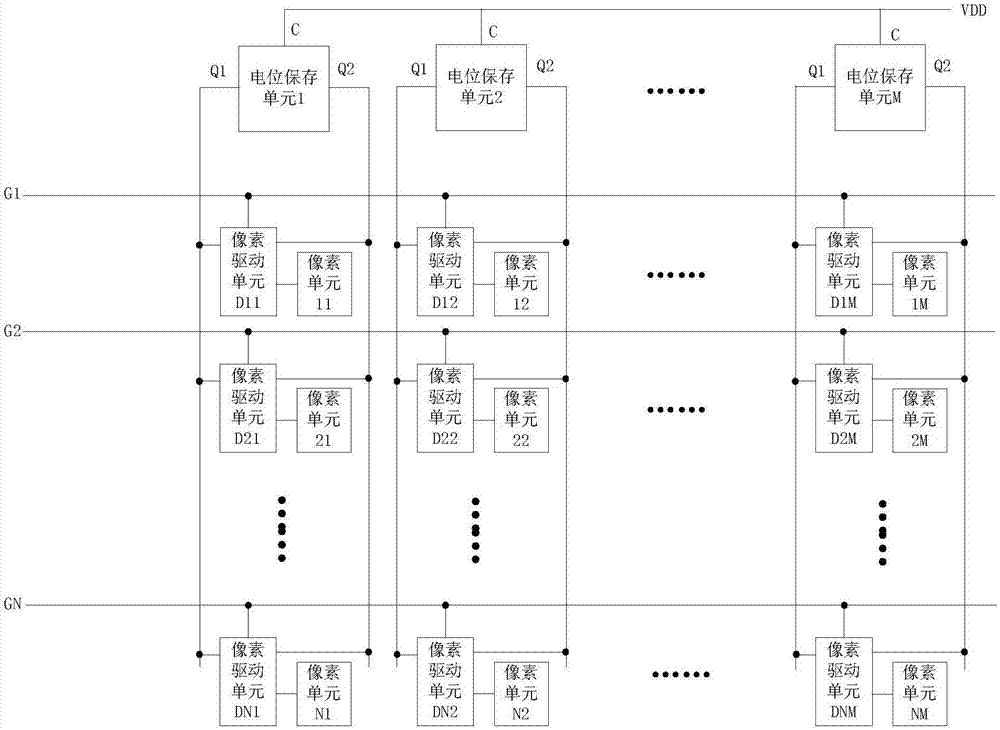
[0026] figure 1 It is a structural schematic diagram of a driving circuit of a display panel according to an embodiment of the present invention.

[0027] In an embodiment of the present invention, the display panel includes N rows and M columns of pixel units, where N and M are both positive integers. Such as figure 1 As shown,


PUM


Abstract

The invention discloses a drive circuit of a display panel, the display panel and a display device. The drive circuit comprises M potential storage units and M columns of pixel drive units, wherein each potential storage unit is arranged corresponding to each column of pixel units, and is used for outputting a first potential signal and storing same at a first potential output end as well as simultaneously outputting a second potential signal and storing same at a second potential output end according to a preset power voltage; each column of pixel drive units comprise N pixel drive units; each pixel drive unit is used for performing drive control on the corresponding pixel unit according to a control signal of a control signal wire, the first potential signal and the second potential signal; therefore, the luminescence control for the display panel can be realized without inputing complex data voltage pulse, the problem of high in power consumption, caused by outputting the complex data voltage pulse, of the drive circuit is effectively solved, and the power consumption of the whole display panel is greatly reduced.

Description


Claims


Application Information

Patent Timeline
Owner BOE TECH GRP CO LTD
Why Eureka
Try Eureka