Automobile projection lamp

A technology for projection lamps and automobiles. It is applied in the direction of motor vehicles, road vehicles, and vehicle parts. It can solve the problems of crowded space under rearview mirrors and doors, no space for projection lamps, and high height of projection lamps. It achieves excellent projection effects. Facilitate automatic identification and picking, small size effect

Inactive Publication Date: 2017-07-07
深圳市纳安特汽车电子有限公司
View PDF6 Cites 0 Cited by
  • Summary
  • Abstract
  • Description
  • Claims
  • Application Information

AI Technical Summary

Benefits of technology

This inventive projector lamps have an innovative way they are designed that makes it easier for people who want their own light bulbs to use them more efficiently while also being able to identify themselves quickly by automatically identifying each individual part with unique codes on top. These lights save time and reduce effort compared to traditional methods like incandescent bulb type lamps. They may even include features such as LEDs instead of filaments to make them brighter than usual. Overall this technology improves efficiency and accuracy during production.

Problems solved by technology

The technical problem addressed by this patented technology relates to finding ways for smaller or less expensive projecting lights that can be used on cars without being too bulky due to their complicated construction and lack of any spaces between themselves. Additionally, these light sources may still require some sort of protection from rainwater damage during use.

Method used


Image

  • Automobile projection lamp
  • Automobile projection lamp
  • Automobile projection lamp

Examples


Embodiment Construction

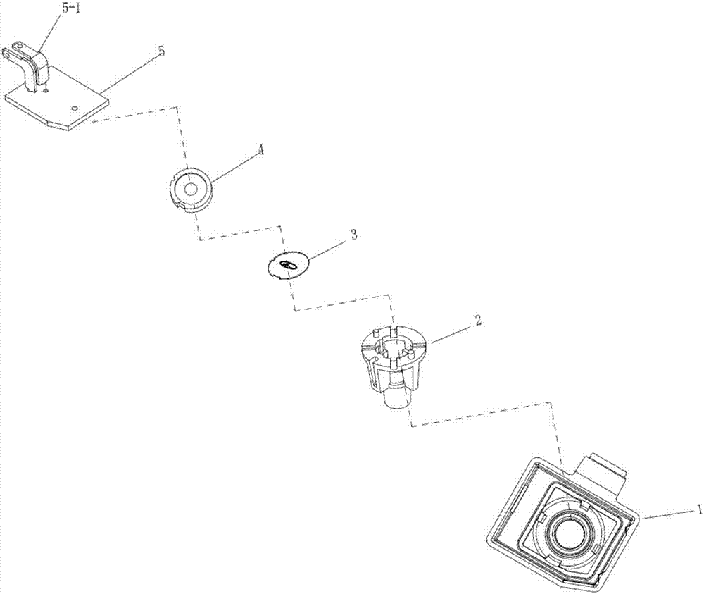
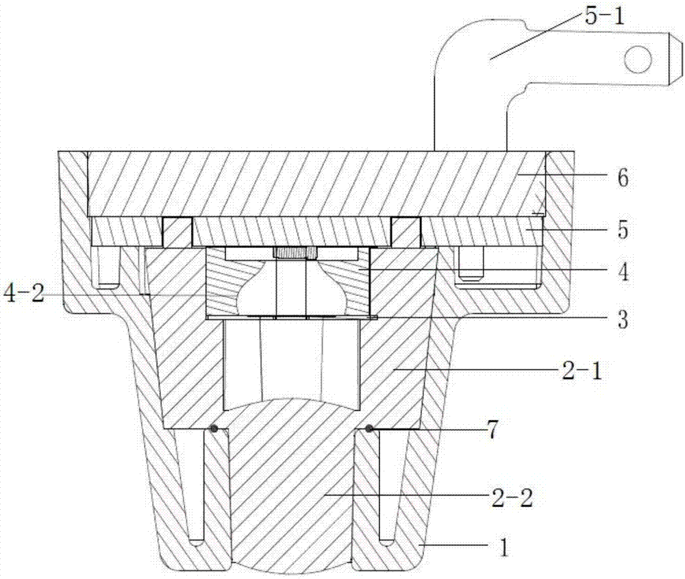
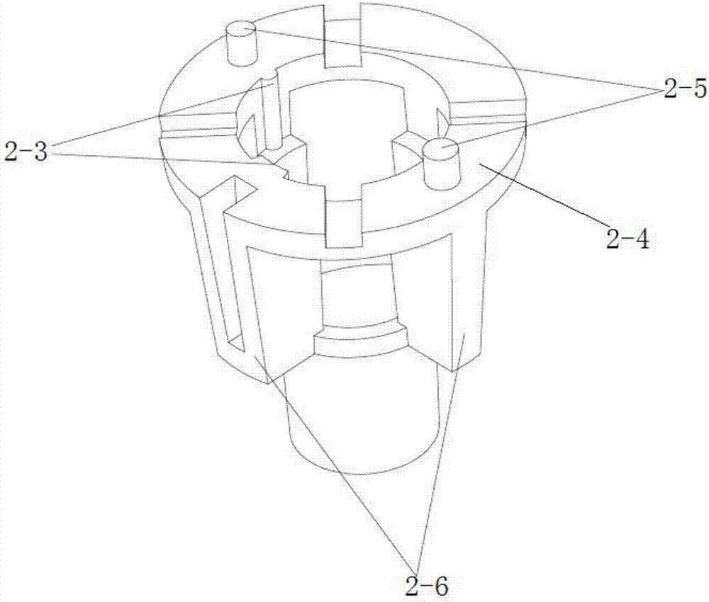
[0024] The present invention will now be described more fully with reference to the accompanying drawings, in which exemplary embodiments of the invention are shown. This invention may, however, be embodied in many different forms and should not be construed as limited to the exemplary embodiments set forth herein. Rather, these embodiments are provided so that this disclosure will be thorough and complete, and will fully convey the scope of the invention to those skilled in the art.

[0025] For ease of description, spatially relative terms such as "upper," "lower," "left," and "right" may be used herein to describe the relationship of one element or feature relative to another element or feature shown in the figures. It will be understood that the spatial terms are intended to encompass different orientations of the device in use or operation in addition to the orientation depicted in the figures. For example, if the device in the figures is turned over, elements described as


PUM


Abstract

The invention discloses an automobile projection lamp. The automobile projection lamp comprises an outer shell, an integrally-formed single lens body with a support, a picture body, a light condensing device, a PCB with an LED and a sealant body, wherein the integrally-formed single lens body with the support is connected inside the outer shell in a sleeved mode, the picture body and the light condensing device are arranged in a containing cavity in the upper part of the integrally-formed single lens body with the support, the picture body is located below the light condensing device, the PCB with the LED is arranged in the part, above the integrally-formed single lens body with the support, of the outer shell, and the sealant body is arranged in the part, above the PCB with the LED, of the outer shell to seal the upper surface of the outer shell. The projection lamp is ingenious and novel in structural design, simple in structure, small in number of application units, excellent in projection effect, extremely small in size and small in height; and in addition, automatic identification and pickup are facilitated, and the labor cost is greatly reduced.

Description


Claims


Application Information

Patent Timeline
Owner 深圳市纳安特汽车电子有限公司
Why Eureka
Try Eureka