Beewax separating device

A separation device and technology of beeswax, applied in the direction of separation methods, precipitation separation, chemical instruments and methods, etc., can solve the problems affecting the separation efficiency and effect of beeswax, low production efficiency, etc., and achieve high separation efficiency and good separation effect

Pending Publication Date: 2017-07-25
河南福美生物科技有限公司
View PDF0 Cites 0 Cited by
  • Summary
  • Abstract
  • Description
  • Claims
  • Application Information

AI Technical Summary

Problems solved by technology

[0002] The separation device of beeswax has a frame, on which a heated stirring device is installed, the stirring device has a wax outlet, and a beeswax separation tank is installed below the wax outlet; in the prior art, the separation of beeswax depends on a long time It has the disadvantage of low production efficiency, which affects the separation efficiency and effect of beeswax

Method used


Image

  • Beewax separating device

Examples


Example Embodiment

[0011] The present invention will be further described below with reference to the drawings and embodiments.

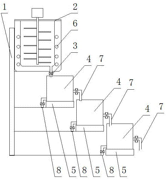
[0012] Such as figure 1 As shown, a beeswax separation device includes a frame 1, on which a heating stirring device 2 is installed, the stirring device has a wax outlet 3, and a beeswax separation tank 4 is installed under the wax outlet; its feature is : A vibrating device 5 is installed below the beeswax separation tank. 6 in the figure is a heating tube, which can heat the stirring device. The invention can realize the rapid layering of beeswax under the action of the vibrating device and realize the invention the goal of.

[0013] Furthermore, there are multiple beeswax separation tanks. Each beeswax separation tank has a middle wax melting outlet 7 and a bottom melting wax outlet 8. The middle wax melting outlet of the previous beeswax separation tank leads to the next beeswax At the entrance of the separation tank, there are multiple vibration devices, and a vibratio


PUM


Abstract

The invention relates to equipment in the technical field of beeswax processing. The name is a beeswax separation device, which includes a frame, and a stirring device that can be heated is installed on the frame. The stirring device has a wax outlet, and a beeswax separation device is installed below the wax outlet. tank; it is characterized in that: a vibrating device is installed under the beeswax separation tank, there are multiple beeswax separation tanks, and each beeswax separation tank has a middle middle wax outlet and a bottom melt outlet, and the last beeswax The outlet of the melting wax in the middle of the separation tank leads to the entrance of the next beeswax separation tank. The vibration device is multiple, and a vibration device is installed under each beeswax separation tank. The amplitude of the multiple vibration devices is from front to back. Weaken successively and increase frequency successively. Such a beeswax separation device has the advantages of good separation effect and high separation efficiency.

Description


Claims


Application Information

Patent Timeline
Owner 河南福美生物科技有限公司
Why Eureka
Try Eureka