Spiral conveyor with auxiliary blades and spiral discharging sedimentation centrifuge

A technology of screw conveyor and auxiliary blade, applied in the field of solid-liquid separation, can solve the problems of low solid content in light phase and poor separation effect, and achieve the effect of low cost, increased area, and improved separation factor Fr

Pending Publication Date: 2021-05-25
JUNENG MACHINERY CHINA
View PDF0 Cites 1 Cited by
  • Summary
  • Abstract
  • Description
  • Claims
  • Application Information

AI Technical Summary

Problems solved by technology

[0004] The applicant aims at the disadvantages of poor separation effect, high solid content in the light phase, and the need for post-treatment procedures to filter or separate solids when the existing equipment groups in the above-mentioned existing production process suspensions that are difficult to separate from solid and liquid. , to provide a screw conveyor with auxiliary blades and a screw discharge sedimentation centrifuge with a reasonable structure. By increasing the equivalent settling area, separation length and increasing speed, the equipment can enhance the processing capacity of the equipment for suspensions that are difficult to separate solids and liquids and separation efficiency, the final light phase has low solid content, and can save space required for equipment, reduce investment and operating costs

Method used


Image

  • Spiral conveyor with auxiliary blades and spiral discharging sedimentation centrifuge
  • Spiral conveyor with auxiliary blades and spiral discharging sedimentation centrifuge
  • Spiral conveyor with auxiliary blades and spiral discharging sedimentation centrifuge

Examples


Example Embodiment

[0029]Example 1:

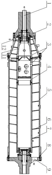
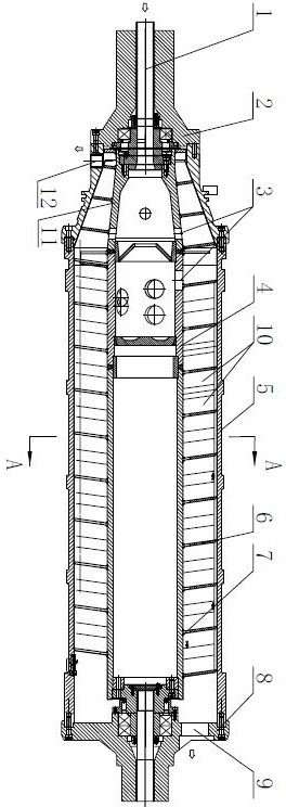
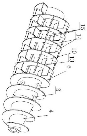
[0030]Such asimage 3 ,Figure 4 As shown, the helical conveyor of the sub-blades of the present invention is between the screw blades 6 of the conventional conventional helical conveyor, which increases several sub-blades 10, and the width of the sub-blades 10 is less than the joint of the spiral blade 6. At the distance, the adjacent two sub-blades 10 are staggered, and the original continuously complete helical channel space between the spiral blades 6 is further separated into a zone flow channel 15, thereby extending the separation path length of the suspension and effectively improves the separation effect.

[0031]In this embodiment, the sub-blades 10 are planar straight blades, along the radial direction of the screw conveyor, and soldered the inner cylindrical 4 outer circumference, one side welding on the spiral blade 6, ie The left edge of a portion of the sub-blades 10 in each helical space is fixed to the left spiral blade 6, and the first gap 13 is left at the

Example Embodiment

[0035]Example 2:

[0036]Such asFigure 5 As shown in the present embodiment, the planar straight blade in the first embodiment is changed to a curved blade, and the sub-blade 10 has a certain bending curvature, and the curved outer convex direction of the curved surface is coincided with the direction of rotation of the drum, that is, the elongation particles in the suspension. Will move along the outer convex surface of the curved blade, such settings can effectively increase the centrifugal force, so that the weight phase particles are easily settled.

Example Embodiment

[0037]Example 3:

[0038]Such asFigure 6 ,Figure 7 As shown, the present embodiment deflects an angle setting of the secondary blade 10 in the first embodiment in the first embodiment.Figure 7 The angle α of the inverse blades 10 and the axis of the drum is 45 degrees, preferably 5 to 30 degrees, adjacent blades parallel, and the deflection direction is consistent. In this embodiment, the sub-bladder 10 is disposed in the rear screw passage of the discharge hole 3, and the transport resistance of the drum cone 11 drying zone can be reduced, and the discharge of the solid phase material can be reduced.


PUM


Abstract

The invention discloses a spiral conveyor with auxiliary blades. A hollow inner barrel is provided with a conical section and a straight barrel section, a feeding hole is formed in the pipe wall close to the conical section, spiral blades are arranged at the periphery of the inner barrel, the plurality of auxiliary blades are arranged between the spiral blades, the width of the auxiliary blades is smaller than the pitch of the spiral blades, and every two adjacent auxiliary blades are arranged in a spiral channel space in a staggered manner to form a zigzag flow channel. The auxiliary blades are additionally arranged between the spiral blades and rotate along with the inner barrel, solid particles of suspension liquid entering the spiral conveyor are separated from a liquid phase under the action of a huge centrifugal force field, and the manner that the liquid is driven to rotate only through the spiral blades originally is changed through the auxiliary blades. The auxiliary blades drive the suspension liquid entering the space between the inner barrel and an outer barrel from discharging holes, so that the centrifugal force and the rotating speed can be immediately obtained, the solid-liquid two-phase separation is accelerated, and the separation efficiency is improved. Meanwhile, the auxiliary blades also increase the equivalent sedimentation area, so that a better separation effect is achieved.

Description


Claims


Application Information

Patent Timeline
Owner JUNENG MACHINERY CHINA
Why Eureka
Try Eureka