Forced vibrating stirrer with balancing block for equal amplitude vibration of stirring shaft

A technology of stirring shaft and balance block, which is applied in the field of forced vibrating mixer equipment, can solve the problems of insufficient vibration stirring effect, poor stress condition of the vibration shaft support bearing, poor sealing of the shaft end of the stirring shaft, etc., so as to achieve easy sealing. , long service life, the effect of improving the stress state

Pending Publication Date: 2017-10-17
CHANGAN UNIV
View PDF3 Cites 1 Cited by
  • Summary
  • Abstract
  • Description
  • Claims
  • Application Information

AI Technical Summary

Problems solved by technology

[0005] The purpose of the present invention is to provide a stirring shaft equal-amplitude vibration forced vibration mixer with a balance block to solve the problems of insufficient

Method used


Image

  • Forced vibrating stirrer with balancing block for equal amplitude vibration of stirring shaft
  • Forced vibrating stirrer with balancing block for equal amplitude vibration of stirring shaft

Examples


Embodiment 1

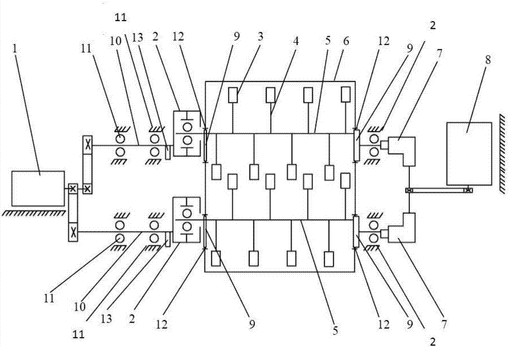
[0031] like figure 1 As shown, the stirring drive device of the vibrating mixer is composed of two identical stirring drive motors 8 and a reducer 7 . The motor shaft of the stirring drive motor 8 is connected with the input shaft of the speed reducer 7 through a belt transmission, and the input shafts of the two speed reducers 7 realize the synchronous rotation of the two speed reducers through the transmission shaft. The output shaft of the speed reducer 7 is connected with the stirring shaft 5, so as to realize the rotation of the stirring shaft during normal operation.

[0032] The vibrating device of the vibrating mixer consists of a vibrating drive motor 1 , a vibrating shaft 10 and a stirring shaft 5 . The motor shaft of the vibration drive motor 1 is connected to the left end of the vibration shaft 10 through a belt drive, and the right end of the vibration shaft 10 is eccentrically connected to the outer ring of a second support bearing 2, which drives the stirring shaf

Embodiment 2

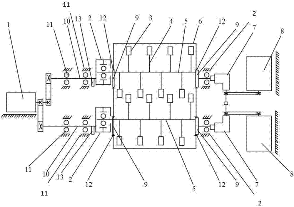
[0036] like figure 2As shown, the stirring drive device of the vibrating mixer is composed of a stirring drive motor 8 and two identical reducers 7 . The motor shaft of the stirring drive motor 8 is connected with the input shafts of the two reducers 7 through a belt transmission, and the two reducers 7 are driven by one stirring motor 8 to realize the synchronous rotation of the two reducers. The output shaft of the speed reducer 7 is connected with the stirring shaft 5, so as to realize the rotation of the stirring shaft during normal operation.

[0037] The vibrating device of the vibrating mixer consists of a vibrating drive motor 1 , a vibrating shaft 10 and a stirring shaft 5 . The motor shaft of the vibration drive motor 1 is connected to the left end of the vibration shaft 10 through a belt drive, and the right end of the vibration shaft 10 is eccentrically connected to the outer ring of a second support bearing 2, which drives the stirring shaft 5 to rotate around the


PUM


Abstract

The invention relates to a forced vibrating stirrer with a balancing block for equal amplitude vibration of stirring shafts. The stirrer comprises a vibration driving motor, a stirring driving motor, a reverse balancing block, a stirring barrel, stirring shafts, a vibrating shaft and reverse eccentric bushings; the two stirring shafts are parallelly arranged in the stirring barrel and are parallel to the inner wall of the stirring barrel; two ends of the stirring shafts penetrate through the stirring barrel; a second supporting bearing is eccentrically arranged on one end of the vibrating shaft, and the left ends of the stirring shafts are mounted in the second supporting bearing; the reverse balancing block is mounted on one end, close to the second supporting bearing, of the vibrating shaft; and the reverse eccentric bushings are arranged between the two ends of the stirring shafts and a shaft hole of the stirring barrel. The stirring shafts are eccentric at two ends relative to the vibrating shaft and the reverse eccentric bushings are additionally mounted, so that the stirring shafts vibrate at equal amplitude all the way in the working process, and therefore, the stirring quality and the sealing effect are improved; meanwhile, the reverse balancing block counteracts the centrifugal force generated due to eccentricity, so that the supporting bearing of the vibrating shaft does not bear an alternating exciting force, and therefore, the service life of the whole equipment is greatly prolonged.

Description


Claims


Application Information

Patent Timeline
Owner CHANGAN UNIV
Why Eureka
Try Eureka