High-speed mixing granulator

A high-speed mixing and granulator technology, applied in the direction of granulation in the static tank/trough, can solve the problems of poor cutting effect of the cutter and poor centrifugal effect of the mixing blade, etc., to achieve improved cutting efficiency, fast cycle speed, and improved The effect of mixing efficiency

Inactive Publication Date: 2020-02-21
吴文地
View PDF4 Cites 0 Cited by
  • Summary
  • Abstract
  • Description
  • Claims
  • Application Information

AI Technical Summary

Benefits of technology

This technology allows for more efficient use of raw material during heat treatment compared to previous methods like placing them vertically or horizontally within an enclosed space inside a tank. By rotating fans around their own axis, these raw materials get lifted above the surface they were sitting down onto while being mixed together. A special type of device called a diffusion-blown cone helps mix this mixture efficiently without leaving any residue behind. Additionally, it introduces a new method where multiple fan blinds are used instead of one single fan blading unit, which further enhances the flow of air through the tower's interior. Overall, this innovative design makes processing crucial components such as raw materials easier and increases overall performance.

Problems solved by technology

This patented technical solution described in the current design involves two issues - firstly, there may exist weak points or areas where particle movement occurs during the process due to gravity; secondly, when the cutting operation takes place over an area called the junction between the tank body and the cup holder, airflow causes these parts to stick together causing difficulty in cleanup efforts.

Method used


Image

  • High-speed mixing granulator
  • High-speed mixing granulator
  • High-speed mixing granulator

Examples


Embodiment Construction

[0021] The following will clearly and completely describe the technical solutions in the embodiments of the present invention with reference to the accompanying drawings in the embodiments of the present invention. Obviously, the described embodiments are only some, not all, embodiments of the present invention. Based on the embodiments of the present invention, all other embodiments obtained by persons of ordinary skill in the art without making creative efforts belong to the protection scope of the present invention.

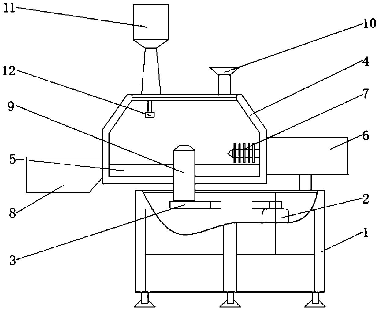
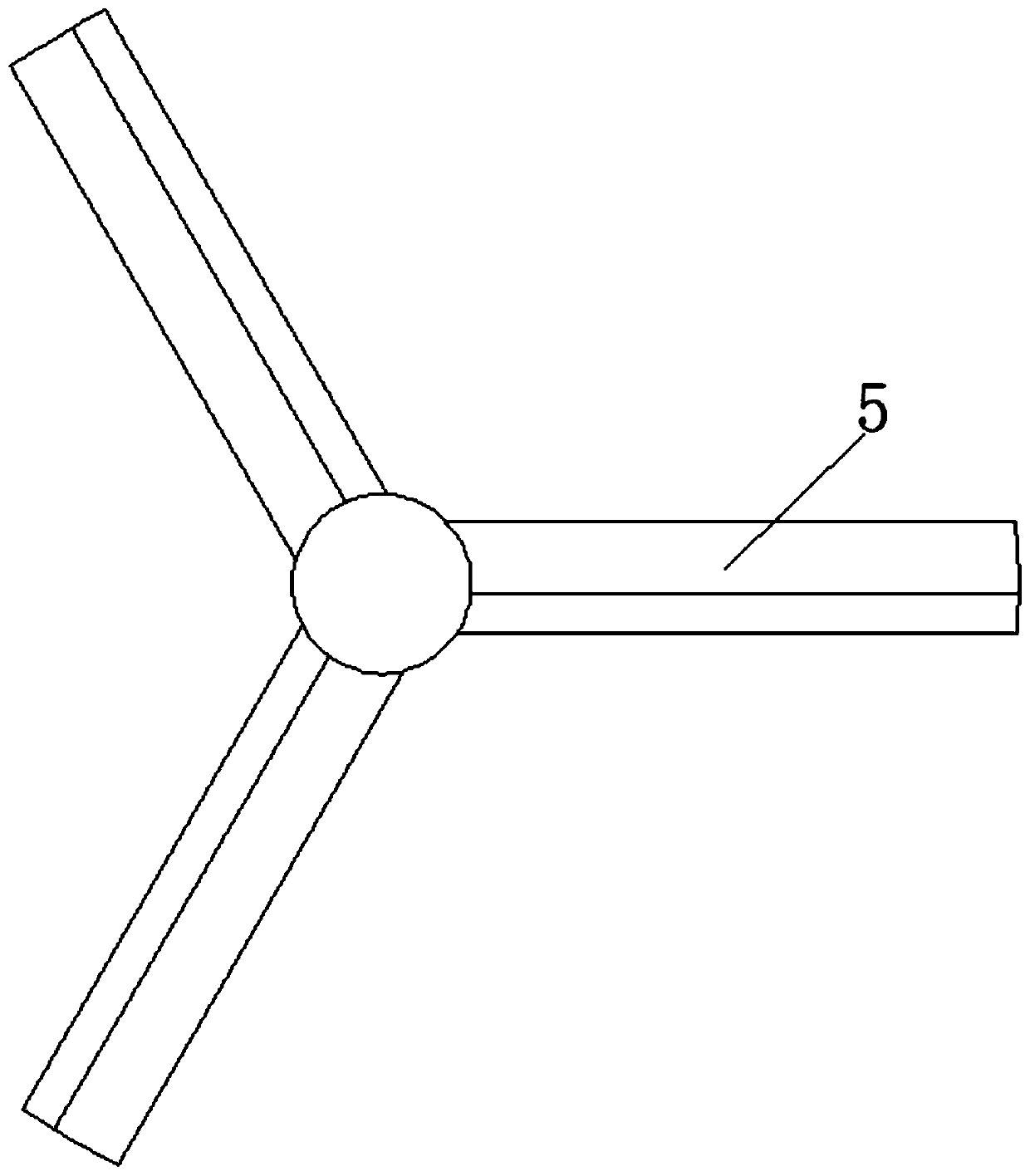
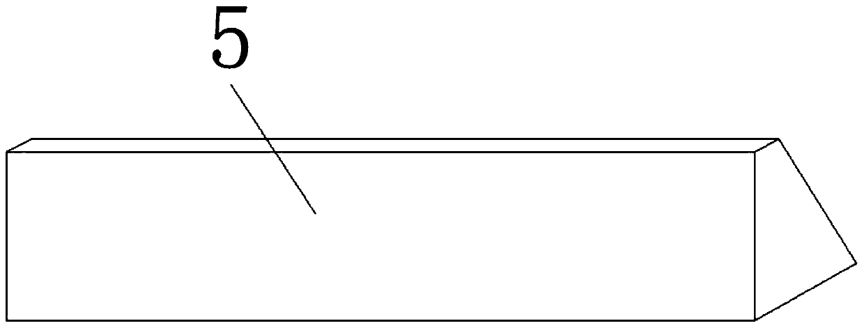
[0022] see Figure 4-6 , a high-speed mixing granulator, including a fuselage 1, a stirring motor 2 is fixedly installed on one side of the fuselage 1, a stirring transmission 3 is movably installed on the top of the stirring motor 2, and an interlayer is fixedly installed on the upper surface of the fuselage 1 One end of the pot 4 and the stirring drive 3 is movably installed with a rotating shaft 9, the outer surface of the rotating shaft 9 is fixedly installed


PUM


Abstract

The invention relates to the technical field of pharmaceutical devices, and discloses a high-speed mixing granulator. The high-speed mixing granulator comprises a machine body, a stirring motor is fixedly mounted at one side in the machine body, a stirring transmission is movably mounted at the top of the stirring motor, a jacketed kettle is fixedly mounted on the upper surface of the machine body, a rotating shaft is movably mounted at one end of the stirring transmission, and fan blades are fixedly mounted on the outer surface of the rotating shaft and are located in the jacketed kettle. Thefan blades are low at the left and high at the right, and the three fan blades are mutually matched and coaxially mounted, so raw materials are accumulated on the fan blades, the raw materials at thebottom of the jacketed kettle can be shoveled up by the lower sides of the fan blades, and the raw materials contained on the fan blades have large outward centrifugal force under the rotation actionof the fan blades; and a fan and the fan blades are coaxially mounted, so wind generated by the stirring transmission blows downwards, the raw materials are diffused all around, and the circulation effect of the blown raw materials in the jacketed kettle is good, thereby the mixing efficiency of the raw materials is improved.

Description


Claims


Application Information

Patent Timeline
Owner 吴文地
Why Eureka
Try Eureka