Welding jig for exhaust manifold heat dissipation auxiliary fixing frame

An exhaust manifold, welding fixture technology, applied in auxiliary welding equipment, auxiliary devices, welding equipment and other directions, can solve the problems of poor welding effect, damage to brackets or flanges, relative movement of flanges and bracket mounting parts, etc. To avoid unstable fixation, avoid injury, and facilitate adjustment

Inactive Publication Date: 2017-11-07
CHENGDU LINGCHUAN SPECIAL IND
View PDF5 Cites 0 Cited by
  • Summary
  • Abstract
  • Description
  • Claims
  • Application Information

AI Technical Summary

Problems solved by technology

[0005] The technical problem to be solved by the present invention is that through manual welding of the bracket, the relative movement of the flange and the mounting part of the bracket is prone to occur, resulting in poor welding effect, or even damage to the bracket or flange. The purpose is to provide exhaust manifold heat dissipation A welding jig for auxiliary fixing frame to solve the above problems

Method used


Image

  • Welding jig for exhaust manifold heat dissipation auxiliary fixing frame
  • Welding jig for exhaust manifold heat dissipation auxiliary fixing frame

Examples


Embodiment 1

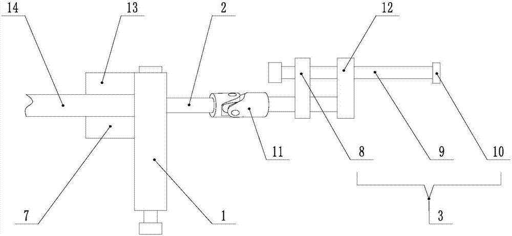
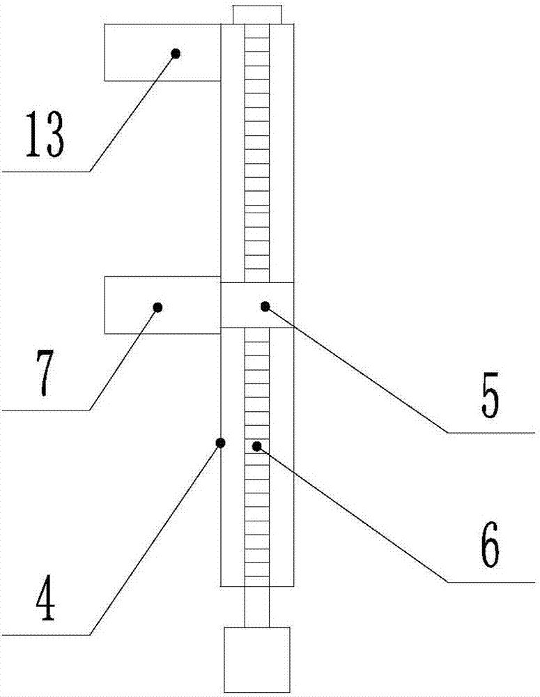
[0023] Such as Figure 1 ~ Figure 2 As shown, the welding fixture for the exhaust manifold heat dissipation auxiliary fixing frame of the present invention includes a fixed part 1, a connecting part 2 and a pressing part 3 connected in sequence, a guide groove 4 is arranged on the fixed part 1, and a The moving block 5 is provided with a screw-6 through the moving block 5, the moving block 5 and the screw-6 are screwed together, and the moving block 5 can move along the screw-6, the moving block 5 is provided with a fixed plate 7, and one end of the guide groove 4 A baffle 13 is provided, and the fixed part 1 is placed on the workbench 14, so that the workbench 14 is located between the fixed plate 7 and the baffle 13, and the screw one 6 is rotated to make the moving block 5 and the fixed plate 7 move along the screw one 6 , that is, the moving block 5 and the fixed plate 7 move along the guide groove 4, so that the fixed plate 7 and the baffle plate 13 clamp the workbench 14...

Embodiment 2

[0026] The present invention is based on embodiment 1, and the present invention is further described.

[0027] Such as figure 1 As shown in the present invention, the welding fixture for the exhaust manifold heat dissipation auxiliary fixing frame, the connecting part 2 is a telescopic rod, and the telescopic rod adopts a common telescopic rod structure on the market, which is used to adjust the length of the connecting part 2 to make it more applicable. The connecting part 2 is provided with a steering mechanism 11, and the steering mechanism 11 can be fixed by a fastener, which is used to adjust the position of the pressing part 3 according to the connection situation of the flange and the mounting part of the support frame, so that the pressing plate 10 has a better pressing effect on the mounting part of the support frame, and the steering mechanism 11 is a universal joint.

Embodiment 3

[0029] The present invention is based on embodiment 1, and the present invention is further described.

[0030] Such as figure 1 As shown, the welding fixture for the exhaust manifold heat dissipation auxiliary fixing frame of the present invention, the guide plate 8 is also connected with the auxiliary guide plate 12, the screw rod two 9 is screwed with the auxiliary guide plate 12, and the screw rod two 9 is simultaneously connected with the guide plate 8 and the auxiliary guide plate The plate 12 is screwed together, so that the movement of the second screw 9 is more stable, the direction is fixed, and shaking is not easy to occur.


PUM


Abstract

The invention discloses a welding jig for an exhaust manifold heat dissipation auxiliary fixing frame. The welding jig comprises a fixing part, a connecting part and a compressing part all of which are sequentially connected. The fixing part is provided with a guiding groove, the guiding groove is internally provided with a moving block, a first threaded rod penetrates the moving block, the moving block and the first threaded rod are screwed, the moving block can move along the first threaded rod, and the moving block is provided with a fixing plate. A baffle is arranged at one end of the guiding groove. The compressing part comprises a guiding plate, a second threaded rod penetrates the guiding plate, the guiding plate and the second threaded rod are screwed, and a compressing plate is arranged at the end, far away from the guiding plate, of the second threaded rod. According to the welding jig, the fixing part is arranged on a workbench, the problem that during manual welding, fixing is instable, and shaking occurs easily can be solved, meanwhile, the operator can be prevented from being hurt, the movement locus of the compressing plate is fixed, shaking is not prone to occur, and the position of the compressing plate is adjusted conveniently.

Description

technical field [0001] The invention relates to a fixture, in particular to a welding fixture for an exhaust manifold heat dissipation auxiliary fixing frame. Background technique [0002] The exhaust manifold is connected to the cylinder block of the engine, and gathers the exhaust of each cylinder into the exhaust manifold, with divergent pipelines. Early automobile engines had low power per unit weight, low fuel combustion efficiency, and the exhaust gas temperature did not exceed 500°C. With the improvement of the efficiency of the automobile engine, the exhaust temperature is increased to 600-650°C. In recent years, the automobile exhaust emission standards have been continuously improved, and the application of catalytic technology and turbocharging technology has significantly increased the working temperature of the exhaust manifold, reaching above 750°C. With the further improvement of engine performance, the working temperature of the exhaust manifold will also i...

Claims


Application Information

Patent Timeline
IPC IPC(8): B23K37/04
CPCB23K37/0443
Inventor 梁静汪庭文
Owner CHENGDU LINGCHUAN SPECIAL IND
Why Eureka
Try Eureka