Anti-spatter laser die-cutting device and method

A laser die-cutting and anti-splash technology, which is applied in laser welding equipment, welding equipment, metal processing equipment, etc., can solve the problems of incomplete dust prevention, unsatisfactory dust removal effect, and inability to achieve sealing, so as to ensure cutting efficiency and cutting quality, dust-proof effect, easy to replace the effect

Pending Publication Date: 2017-11-17
GUANGDONG YI XINFENG INTELLIGENT EQUIP CO LTD
View PDF6 Cites 2 Cited by
  • Summary
  • Abstract
  • Description
  • Claims
  • Application Information

AI Technical Summary

Benefits of technology

This patented technology describes various technical featments related to improved performance of a lasering system (LFS). These improvements include increased safety against environmental factors such as rain, snow, wind, and vibration; enhanced coolant delivery due to better control over temperature and humidity levels near the work area; reduced noise caused by the use of reflective materials instead of metal plates like aluminum mirrors, resulting in higher image clarification and clearer visualization than previous methods. Additionally, there may exist other techniques associated with the LSF including setting up guards around the rod ends and removing debris from them beforehand. Overall, these technologies enhance the overall functionality and lifespan of the Laser System.

Problems solved by technology

This patents describes different ways that can improve the quality of lithi ion cells used today. One way involves improving their properties while maintaining them at reasonable cost levels. Another method includes adding extra components like electrodes inside the cell itself instead of just making up everything beforehand. Additionally, some manufacturers also provide specialized tools called laser heads to clean these materials effectively without any issues related to contamination caused by external factors like dirt particles.

Method used


Image

  • Anti-spatter laser die-cutting device and method
  • Anti-spatter laser die-cutting device and method
  • Anti-spatter laser die-cutting device and method

Examples


Embodiment Construction

[0035] The present invention will be further described below in conjunction with the accompanying drawings.

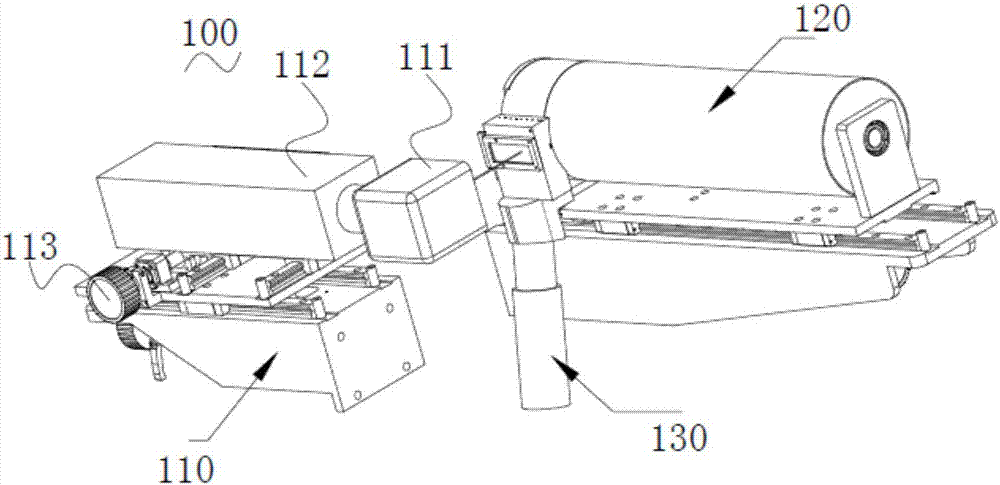
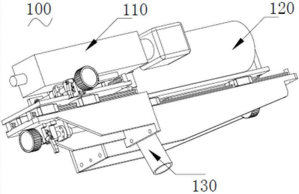
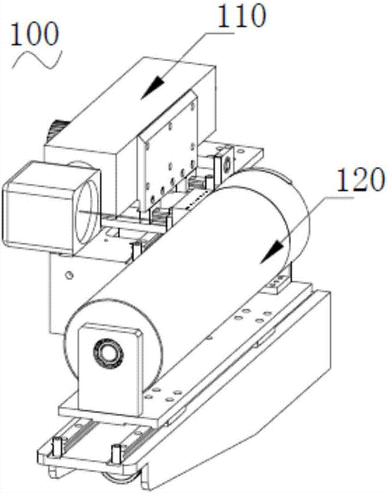
[0036] Such as Figure 1 ~ Figure 3 As shown, they are perspective views of different viewing angles of the anti-splash laser die-cutting device of the present invention.

[0037] The anti-splash laser die-cutting device 100 includes a laser cutting unit 110, a pole piece conveying roller 120 corresponding to the laser cutting unit 110, a dustproof unit 130 installed between the pole piece conveying roller 120 and the laser cutting unit 110, and the laser cutting unit 110 includes a laser head 111, and the dust-proof unit 130 includes a glass block 131 that is arranged facing the laser head 111 and located between the laser head 111 and the pole piece conveying roller 120 for laser light to pass through and to prevent dust from passing through. The laser cutting unit 110 emits laser light to die-cut the pole piece on the pole piece conveying roller 120, and the dust gene


PUM


Abstract

The invention relates to the field of battery pole piece die cutting, in particular to an anti-spatter laser die-cutting device and method. The anti-spatter laser die-cutting device comprises a laser cutting unit, a pole piece conveying roller corresponding to the laser cutting unit, and a dust-proof unit mounted between the pole piece conveying roller and the laser cutting unit, wherein the laser cutting unit comprises a laser head, the dust-proof unit comprises a glass block plate, and the glass block plate is right opposite to the laser head, located between the laser head and the pole piece conveying roller and used for letting laser pass through and preventing dust from passing through. Dust generated in the die-cutting process is blocked by the glass block plate of the dust-proof unit and accordingly prevented from adhering to a pole piece; on one hand, the anti-spatter laser die-cutting device is good in dust-proof effect and beneficial to the improvement of the quality of the pole piece, and on the other hand, the die-cutting device is simple in structure and low in manufacturing cost.

Description


Claims


Application Information

Patent Timeline
Owner GUANGDONG YI XINFENG INTELLIGENT EQUIP CO LTD
Why Eureka
Try Eureka