Energy efficiency joint optimization method in MU-MIMO wireless energy/data transmission

A wireless energy and data transmission technology, applied in radio transmission systems, transmission monitoring, wireless communication, etc., can solve the problems of data transmission rate impact, complex optimization problems, reduce the advantages of MIMO technology energy consumption optimization, etc., to expand the scope of application, The effect of improving energy efficiency

Active Publication Date: 2017-12-01
CERTUS NETWORK TECHNANJING
View PDF3 Cites 7 Cited by
  • Summary
  • Abstract
  • Description
  • Claims
  • Application Information

AI Technical Summary

Problems solved by technology

Energy consumption optimization involves two aspects: ① Optimization target selection problem
However, in addition to the impact of power on the data transmission rate in the MIMO system, the number of space division channels (depending on the number of user terminal antennas) will also affect the data transmission rate
Therefore, the degree

Method used


Image

  • Energy efficiency joint optimization method in MU-MIMO wireless energy/data transmission
  • Energy efficiency joint optimization method in MU-MIMO wireless energy/data transmission
  • Energy efficiency joint optimization method in MU-MIMO wireless energy/data transmission

Examples


Embodiment Construction

[0018] In order to make the object, technical solution and advantages of the present invention clearer, the present invention will be further described in detail below in conjunction with the accompanying drawings and embodiments. It should be understood that the specific embodiments described here are only used to explain the present invention, not to limit the present invention.

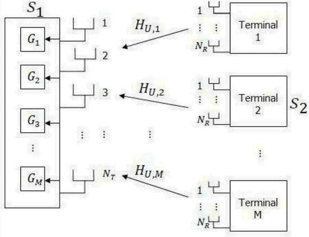
[0019] Such as Figure 1 to Figure 5 As shown, this embodiment is a method for resource allocation in a multi-user MIMO wireless energy / data transmission system, the method includes the following steps:

[0020] Step 1. Analyze system workflow protocol

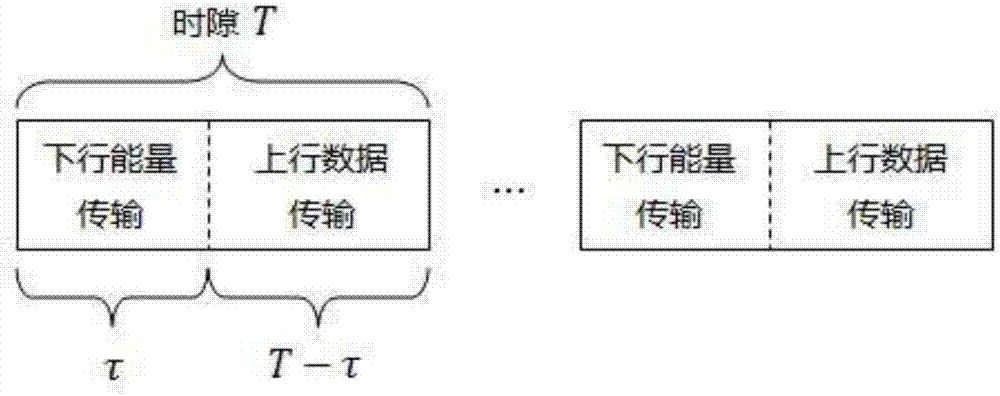
[0021] Such as figure 1 As shown, the entire multi-user MIMO wireless energy / data transmission system works periodically in time slots, and the time slot length is T. During the first τ time of each time slot, the system performs downlink wireless energy transmission; during the later (T-τ) time, the system performs uplink data transmission. τ


PUM


Abstract

The invention discloses an energy efficiency joint optimization method in MU-MIMO wireless energy/data transmission. The method takes the uplink/downlink work switching point and the base station sending power into consideration, and comprises the following steps: a user terminal firstly receives the energy sent from a base station, and then sends the data by using the energy to the base station. The optimization target of the method is the maximum system energy efficiency, the maximum system energy efficiency represents that the system can perform the most data transmission by using the least energy, and shows the optimization of the system. In the system energy efficiency optimization process, the problem is subjected to equivalence by using the Lagrangian duality theory, and then the problem is resolved by using an iteration algorithm based on the Dinkelbach algorithm, thereby acquiring the optimal energy efficiency.

Description


Claims


Application Information

Patent Timeline
Owner CERTUS NETWORK TECHNANJING
Why Eureka
Try Eureka